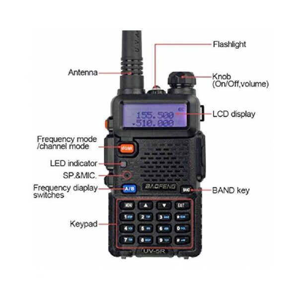
How to Manually Program a Baofeng Radio to a Repeater.
Programming a Baofeng handheld radio to a repeater can be a useful skill to have, especially if you are a radio enthusiast or are using the radio for emergency communication. In this article, we will go over the steps to program a Baofeng radio by hand, where to find the necessary information, and some tips to make the process as smooth as possible.
Gather the necessary information:
The frequency, offset, and tone of the repeater you want to program into your Baofeng radio. This information can typically be found on the repeater’s website or through a local amateur radio club.
The model number of your Baofeng radio. This can be found on the back of the radio or in the user manual.
Enter programming mode:
Turn off the radio.
Press and hold the “Menu” button while turning on the radio.
Release the “Menu” button when the display shows “Frequency Mode.”
Input the repeater information:
Use the up and down arrow buttons to navigate to the desired memory channel.
Press the “Menu” button to enter the memory channel programming mode.
Use the up and down arrow buttons to navigate to the “RX Freq” field.
Enter the repeater frequency using the keypad.
Press the “Menu” button to move to the next field.
Use the up and down arrow buttons to navigate to the “Offset Freq” field.
Enter the repeater offset frequency using the keypad.
Press the “Menu” button to move to the next field.
Use the up and down arrow buttons to navigate to the “Tone” field.
Enter the repeater tone using the keypad.
Save the repeater information:
Press the “Menu” button to exit the memory channel programming mode.
Use the up and down arrow buttons to navigate to the “Save” field.
Press the “Menu” button to save the repeater information to the memory channel.
Test the repeater connection:
Turn off the radio and turn it back on.
Use the up and down arrow buttons to navigate to the memory channel with the repeater information.
Press the “Push-To-Talk” button and speak into the microphone to test the connection with the repeater.
Some additional tips for programming a Baofeng radio:
Make sure to double-check the repeater information before saving it to the memory channel to avoid any errors.
It may be helpful to write down the repeater information on a piece of paper or in a notebook to reference while programming the radio.
If you are having trouble programming the radio, try consulting the user manual or reaching out to a local amateur radio club for assistance.
Consider purchasing a programming cable and programming software to make the process of programming the radio easier and more efficient.
I hope this article has been helpful in explaining the steps to program a Baofeng radio to a repeater by hand. With a little bit of patience and attention to detail, you can easily program your Baofeng radio to connect to a repeater for enhanced communication.
hamadmin
PiStar 4.x GPS (Troubleshooting and Adding GPS to PiStar)
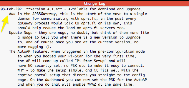
Ladies and gents, this is a quick post showing you how to troubleshoot your GPS to ensure that you are indeed getting data from the GPS module, As you know or perhaps are unaware on Version 4.2.1 (may-2020) PiStar got an update and it had a Mobile GPS option, there was also some talk a year before of folks adding their scripts to get the data onto aprs.fi, since that was closed as seen here, I did not even play with that script or continued its development both because of covid as well as it seemed that the person developing it simply gave up after speaking with someone, only GOD knows what happened there, anywho, I saw that version 4.1.4 (Feb 2021) got a start for a more efficient way of communicating with aprs.fi. So I decided to play with it and see what it’s all about once more, but I ran into a problem, and it’s why I am writing this for those that wish to play with it as well.
I will be using a cheap USB GPS module that I use for my other projects.
As of this writing, this dongle is $14.99 with free shipping if you have prime as I do. Go ahead and make sure that your PiStar has the latest 4.x software, since we are only focusing on simple troubleshooting and setup, I will not go over anything else other than the GPS module and the software.
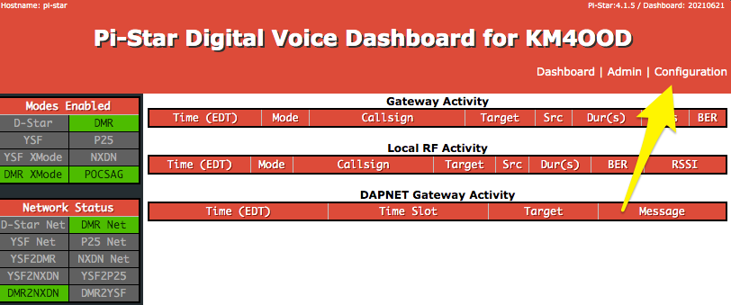
Attach the USB Dongle to the RPI, if you have an RPI Zero, go ahead and also get an adapter as mentioned in the hardware list. Restart or boot up your RPI, Once it’s fully up and running navigate to “Configuration”
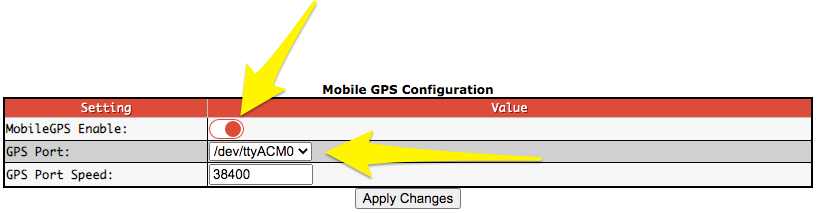
It may prompt you to add your credentials, if you haven’t changed them they are “pi-star” for the username and the password is “raspberry” be sure to change these to something more secure, in this page at the bottom you will find the two fields to do so, then once you are there at the configurations page, scroll down to “Mobile GPS Configuration”
Here you can enable the GPS as well as select the GPS port, if you have chosen the same GPS Dongle that I have, then it should be /dev/ttyACM0 <– that’s a Zero, once you enable and click Apply Changes it should start to work.
Seems too simple, doesn’t it, well for me I had an issue with mine and it came as a dud, I did however manage to pull one from my other computer that runs my FT8 as I use this to keep my FT8 computers time synced with the GPS time, far more accurate than using an NTP server, anywho….. I had to pull up the terminal, you can do this on a mac or a Linux machine easily or if you have a mobile phone or a windows machine perhaps you may want to use the web SSH found under the “Expert” tab. Bellow, I will show you your options to get a CLI.
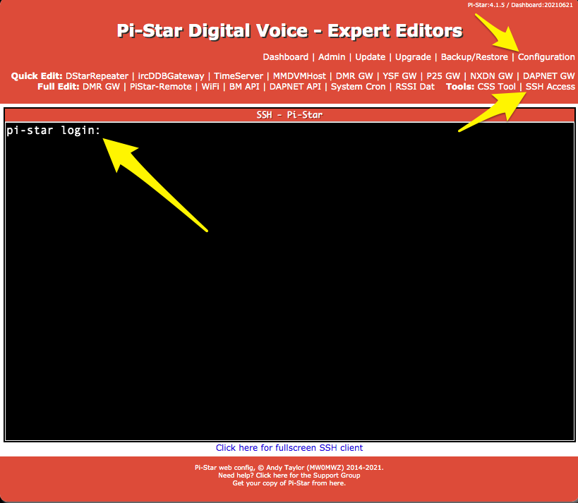
Web SSH:
Go to Configuration / Expert / SSH Access ( don’t forget your credentials, if you haven’t changed these its pi-star / raspberry )
Terminal:
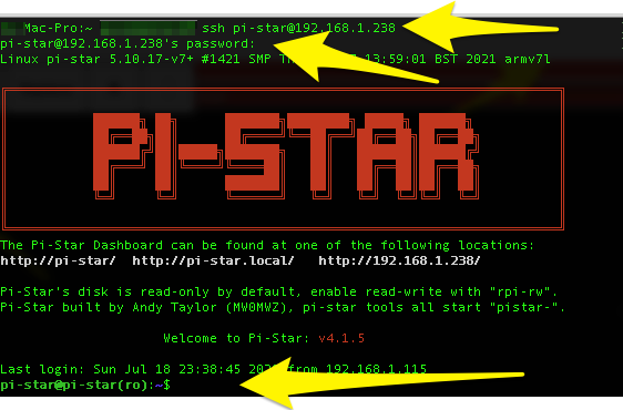
On the terminal all you need to do is run this command, we are assuming you know the IP of your RPI in this case.
sudo ssh pi-star@192.168.1.238 <——– replace this IP address with yours, I am using this as our tester IP for this tutorial.
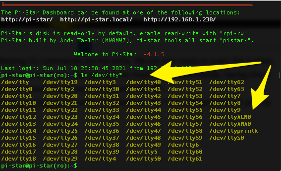
Regardless of where you are the following CLI commands are the same. We are now ready to query the system, remember the RPI (Raspberry Pi) is simply a Linux box that you can run most Debian commands, having this in mind. I will run the following command to check what I had connected to the RPI. ls /dev/tty* <— this command will list anything that is within this location, the * is a wildcard and will pick up anything that is labeled ttyblah blah blah. there we will find the ttyACm0
In my case, this told me that the OS did see the hardware connected to it, so I wondered why I wasn’t getting any data from it, so I ran a command to see if it was indeed getting data from the GPS satellites.
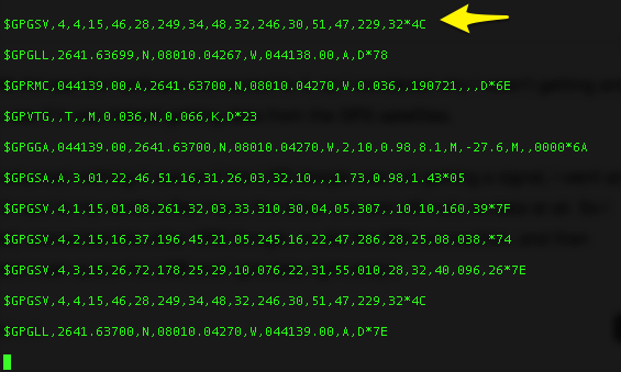
I ran “sudo cat /dev/ttyACM0” this returned nothing it was as if the USB dongle was not getting a signal, I went and used a USB extended cable to put it next to my window like I have the other one and still null, no data at all. So I grabbed the other one and rebooted, connected the other GPS Dongle, re-did the SSH connection, and then verified, came back to the spot where I can query the USB and I got data right away!.
This is when I knew I had a bad device, then for good measure, I went ahead and grabbed this dongle and place it onto the RPI without the extension cable, I ran into the same issue I had where the signal was not that great but I still managed to get some NEMA Data, I placed everything back how it was, requested Amazon to give me a return label and after two days I got my replacement, I added it to the RPI and it started to work. I even got a USB extension cable so I could put this one next to the other, it also gave me an idea of using one GPS device for two devices but that’s another project for the future. I hope this helps anyone that runs into this issue with any GPS device you wish to add onto an RPI or for this example on a Pistar that will be stationary at times and at other times it will be on the road. Oh, I forgot to mention if you want to close the cat command to stop listening to the GPS module, simply hit CTRL + C.
And… now I wait for more support and see if this works in a few days when I use my hotspot on the road. 😉
hamadmin
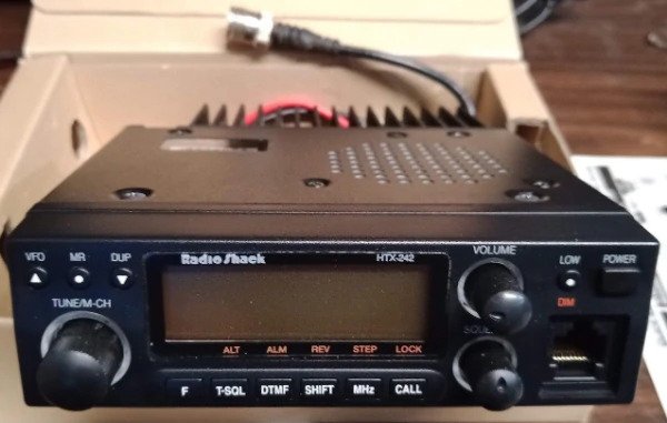
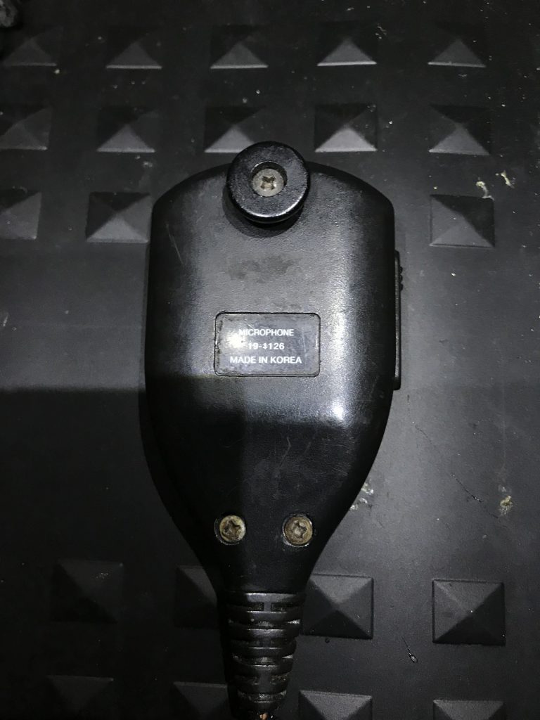
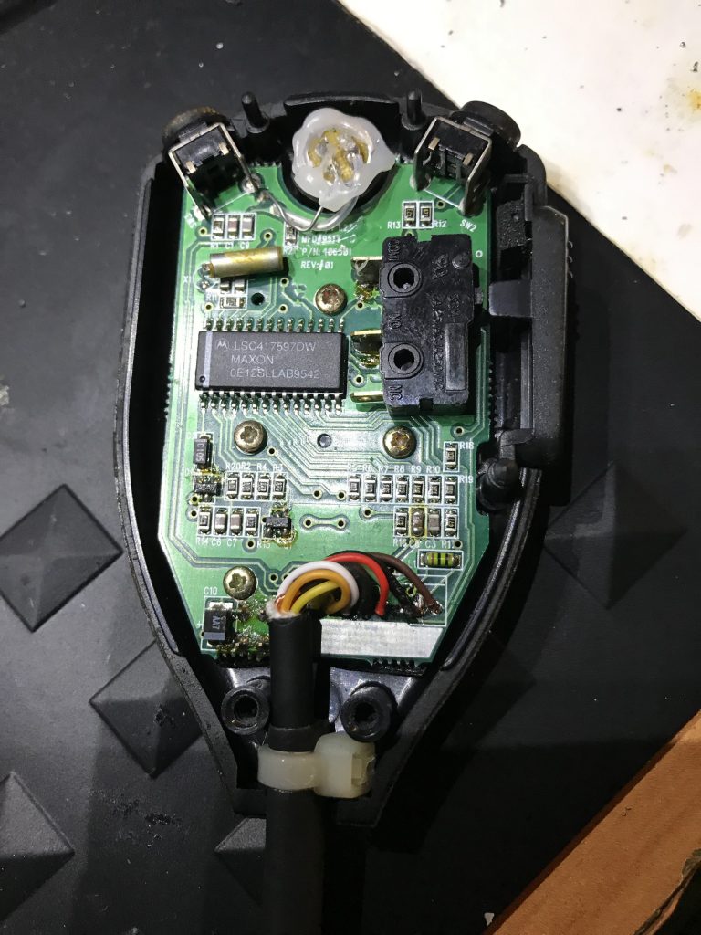
Radio Shack HTX-242 MIC Repair (MIC Part 19-1126)
After a Ham Flea Market, I picked up this old 2M Radioshack Radio for 20$, I took it home and tested it and it works like a charm, I cleaned it up, the image above. Unfortunately, it suffers the same fate as any other of its kind and that was the coiled cable for the MIC it was chewed up and had electrical tape (vinyl tape) as well as some sections with small zip ties. Well, I couldn’t keep it in this form so this article focuses on the restoration of the microphone for this old radio.
Tools: Soldering Iron Heatgun or Rework Machine #2 Phillips screwdriver #0 Phillips Screwdriver Hot Glue Gun Cable Cutters Multimeter to test any two points for any shorts when soldering. * No other pin should show continuity.
Materials:
Small Zip Tie Solder Solder Flux Shrink Tubing Microphone 8 pin Cable ( Click me I am a link)
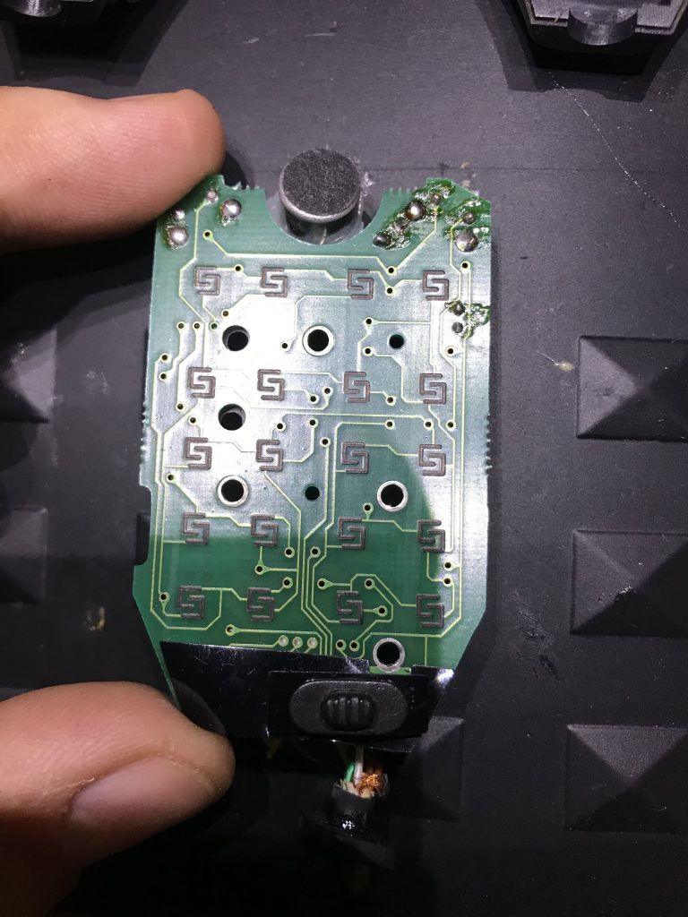
Step One: Remove the three screws on the rear of the MIC.
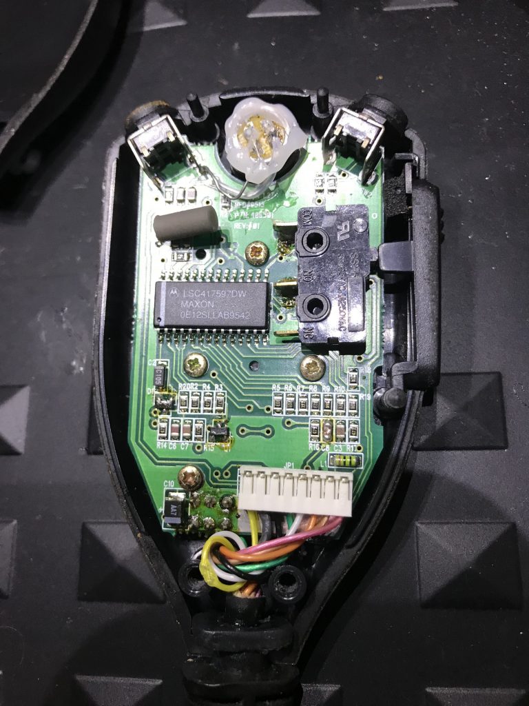
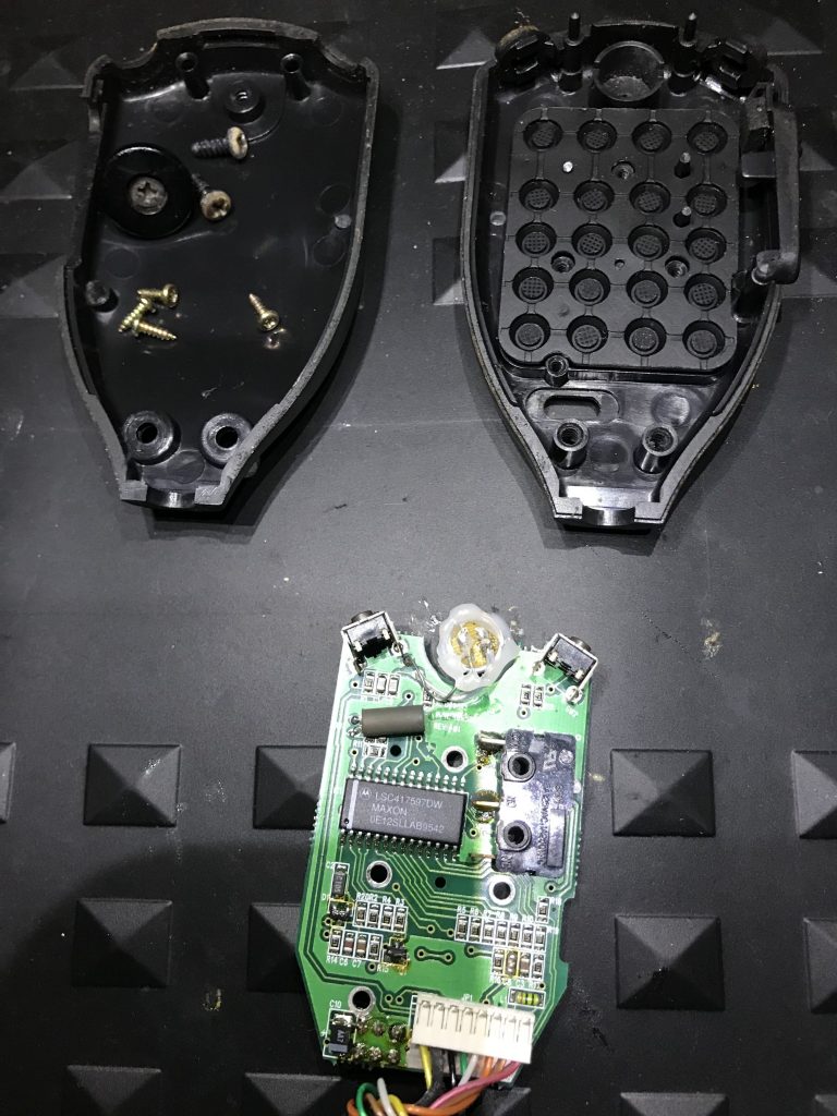
Step Two: Remove all 4 screws holding the PCB onto the MIC Case. Note* Take good caution for the buttons and surface mounted components.
Step three: Remove the PCB from the Housing.
Step four: Remove the slider switch and the two small plastic slider covers with care.
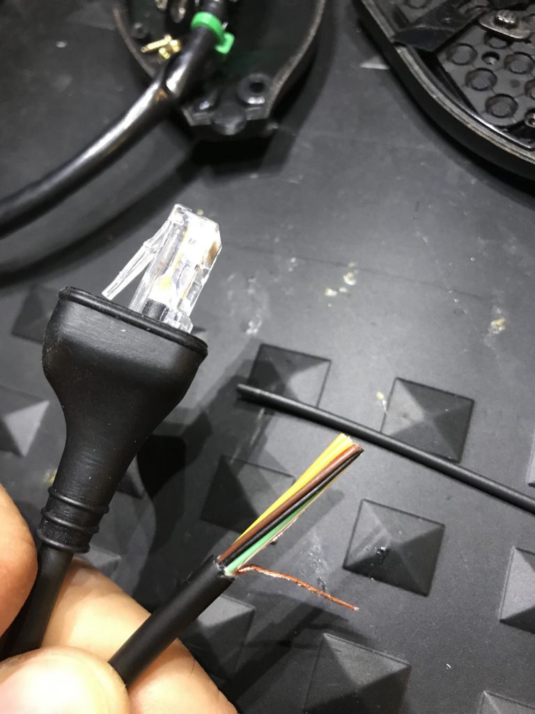
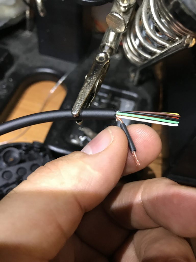
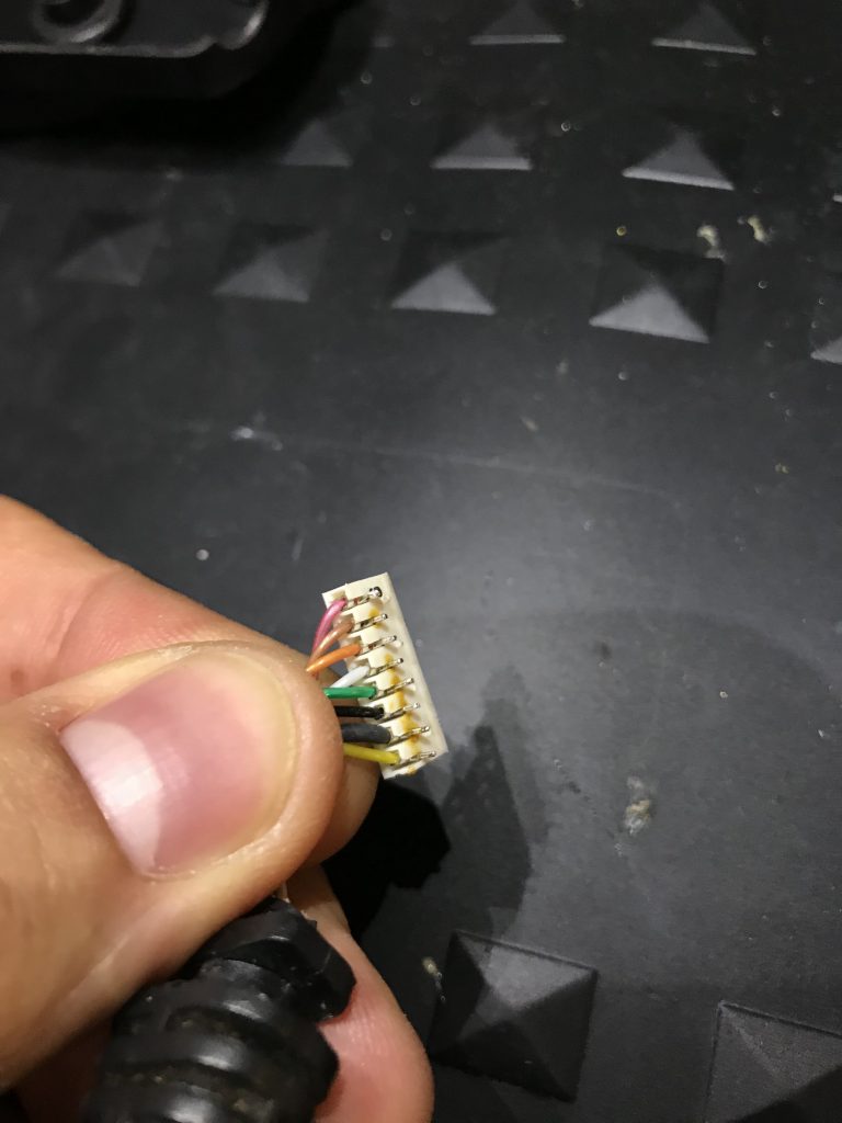
Step Five: Cut one end of the 8 Pin Coil cable and strip the ground then add a small shrink tube to protect it from shorting anything else. Also without heating up add some shrink tubing for later use as a strain relief on this end just push it to the side for later use.
Step Six: Use a heat gun or in my case, I have a workstation so I used that at a low temp so as not to damage other conductors.
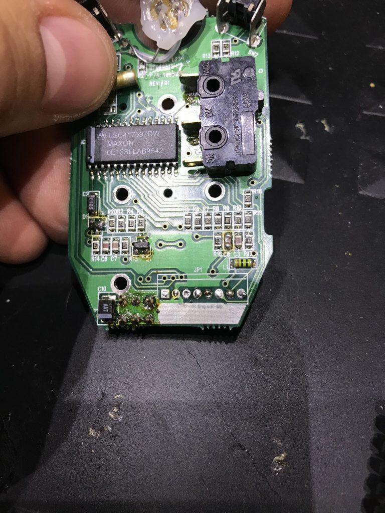
Step Seven: With caution remove the 8 pin header by applying solder flux and using a chisel tip then run the tip of the solder gun back and forth while applying some force. You will find that it will slowly come off the PCB board leaving no trace or marks. The key is to be patient.
Step eight: Clean the PCB with some Electronics Grade Isopropyl alcohol, a small bristle brush does not hurt 😉
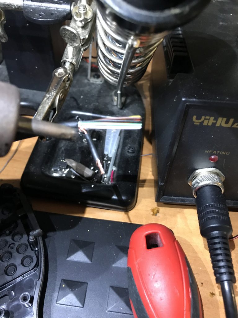
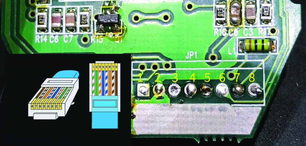
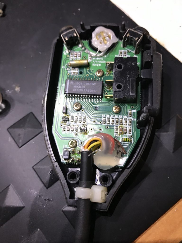
Step 9: This is the good part. Here you see the pins in relation to the 8 pin RJ45 Connector. Please disregard any color coding used by the manufacturer as I saw this not matching the factory MIC color code. Solder each of the conductors carefully and with patience, leaving at least 1″ of spacing for our “service loop”.
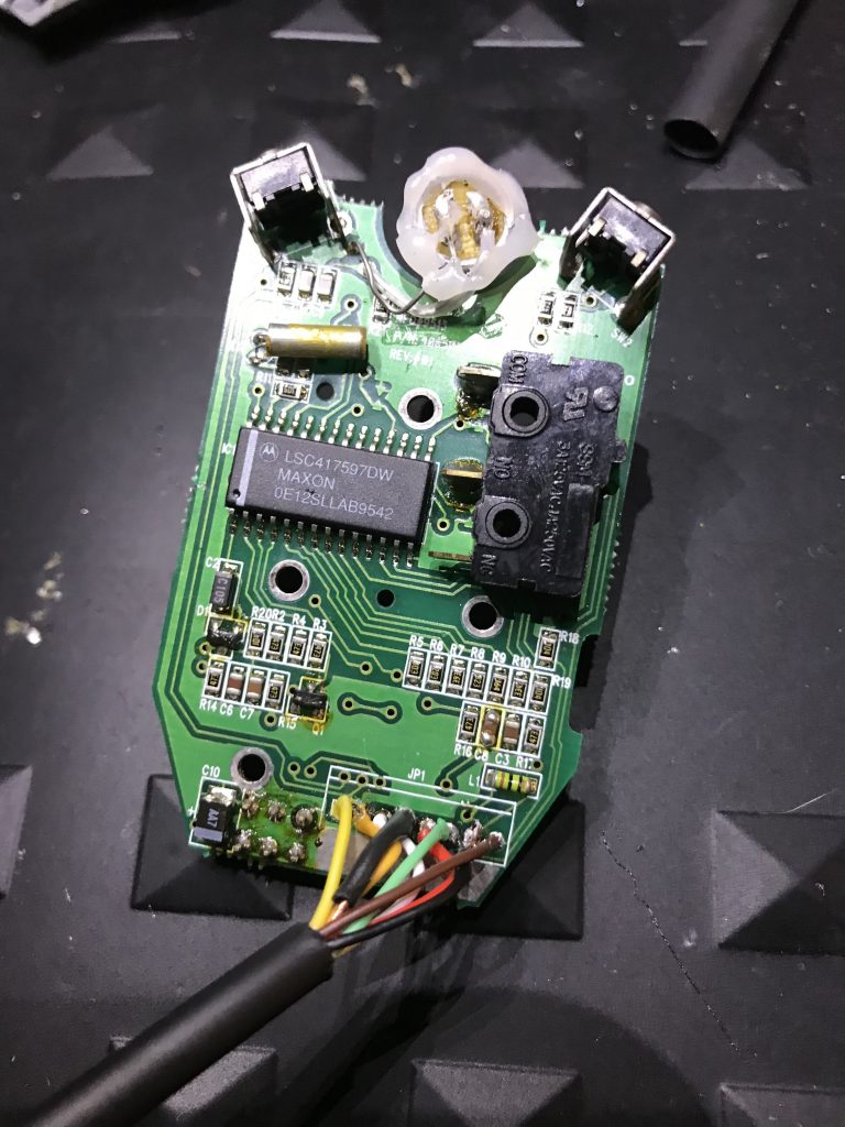
This is the image of the Soldering Completed.
Step ten: With care make your service loop add a small zip tie for strain relief, Here you can also see the shrink tubing added earlier in {step 5} for help with any strain as well.
Step 11: I added some hot glue to protect the joins from any movement wear.
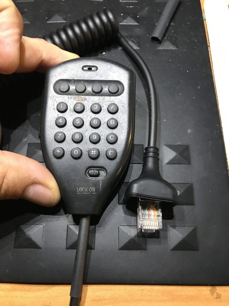
Put it all back together and here is the end product.
It works like a charm!
hamadmin
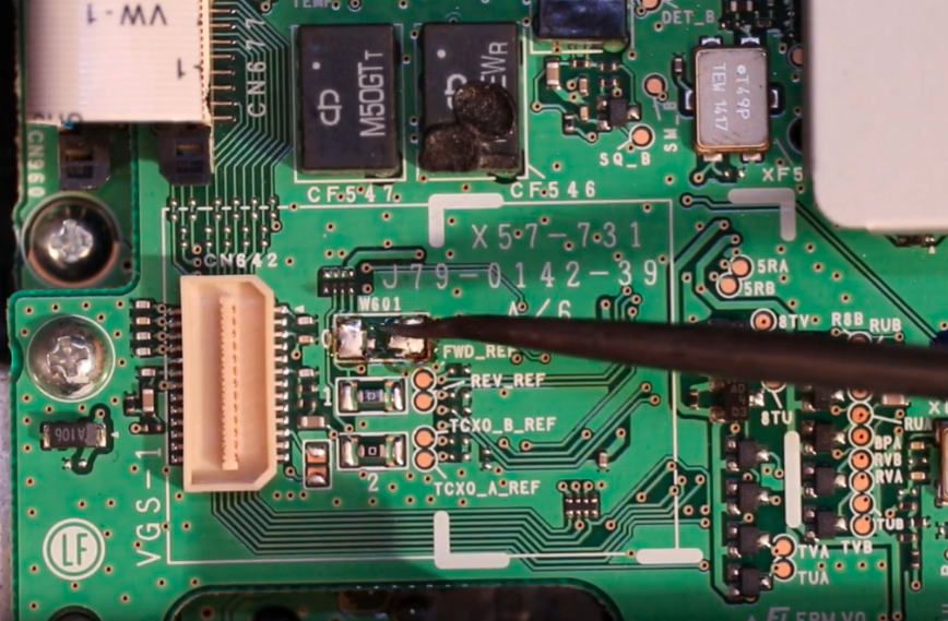
Mars Cap Mod for Kenwood TM-V71A
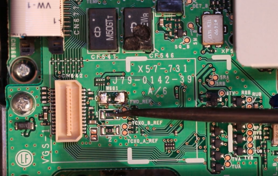
Expanded Transmit Modification for TM-V71A To open the transmit on this radio, you have two options for the frequency range you want to open up. For either option, start by opening the radio: Place the radio on the bench with the speaker side up and the front of the radio facing toward you. Remove the 8 screws that hold the top cover on the radio. Look in the lower left-hand corner (closest to the control head on the left-hand side of the radio). Notice a green wire labeled “W601” and two chip resistors labeled “1” and “2”.
Option 1Option 2
Here are your two options:
option 1) For transmit between 142-151.995 and 420-449.995 remove green wire W601. Either unsolder to remove the wire, or cut it and tape it to prevent the wire from touch anything else inside the radio.
option 2) For transmitting between 136-174 and 400-470 MHz remove W601 as above. Also, remove the 0-ohm resistor labeled “1” which is just in front of W601.
And VOILA! you have a fully open radio.
hamadmin
10 Minute Script for Linux and Mac OSX
So today I was cleaning up some of my scripts and found this little gem, a simple script that would send a voice with my callsign out through the speakers, since I own a Signalink the audio output of this would trigger my radio and thus keeping me “part 97 legal”, Its just for kicks nothing special here but others may find it useful, you can edit the script for your makeshift repeater or simply have it transmit while you start a conversation and have it remind you or simply call out your callsign.
#!/bin/bash

# Written by Jose Malave KM4OOD

callsign=KM4OOD

while true

do

# Change the CallSIGN WITH YOUR OWN

say This is $callsign

# 10 Minutes = 600 Seconds

sleep 1

done
hamadmin
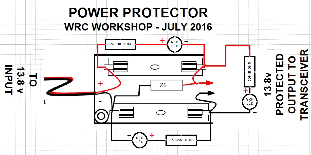
POWER CIRCUIT PROTECTOR WORKSHOP 7/16/2016
Today we created a circuit that will protect your Ham Radio from any surges, just for about 5-8$ worth of parts.
Lets take a look at the items needed to complete this project.
After much deliberation, there was something about this circuit that was limiting my power output. I will be going over this circuit at a later date and find where it was limiting my amperage.
hamadmin
Ham Radio Pager (Dapnet)
A few years ago I found myself reading an article about pagers and how there are a few that can be programmed to be on the 70CM band after some research I found that there was a project to add the DAPNET to the Brandmeister system. I went ahead and ordered a pager and started to fiddle with my Hotspot running Pistar and got it to work. Below are the notes that I had with some screenshots, note that some of the information was taken from the DAPNET site with images and videos created by me today to illustrate how easy it is to set up.
I used this pager ( you can have the seller program your pager or get the programmer, I chose to have both done as it was free programming and the programmer would be good for later use.
If you already have a running pi please update and Upgrade Pi*’s base system services and packages
Login to your Pi* Installation via SSH using Terminal,cmd-Prompt or putty (Standard is „ssh pi-star@pi-star“ (you can miss the:22 at the end because it is the standard port)
ssh pi-star@pi-star [Enter]
Now you will be asked for the Password – Standard-Password is „raspberry“ without „“ or take the password you have changed in Pi-Star Dashboard.
You will see the Welcome Message in ASCII-Signs
Now you have to Enter the following commands:
1. PI* uses write protection so the command to unlock the filesystem for editing is:
rpi-rw [Enter]
2. Now get the latest Version of Pi* and all needed software components:
sudo pistar-update [Enter]
3. Upgrade the Pi* Installation to the next following Version:
sudo pistar-upgrade [Enter]
Repeat the last command (sudo pistar-upgrade) till you get a message „you have installed the latest version of Pi* – No update needed“ or a similar message.
It is not possible to directly upgrade to the newest version! So you have to repeat the pistar-upgrade several times.
For example, You have installed Pi* Version 3.4.13 and want to get onto Version 3.4.16
You have to use the command „sudo pistar-upgrade“ 3 times to get from 3.4.13 to 3.4.14, then from 3.4.14 to 3.4.15 and 3rd time to get from 3.4.15 to 3.4.16.
The last output in the terminal should be:
    You are already running the latest version…
    Sleeping a few seconds before making the disk Read-Only…
    Finished
Upgrade the firmware of your MMDVM-Hardware
for Upgrading MMDVM_HS_Hat board connected to GPIO you have to enter the command:
sudo pistar-mmdvmhshatflash hs_hat
for upgrading the original MMDVM-HS_DUAL_HAT board (made by Andy, Florian (DF2ET) and DB9HAT) connected to GPIO you have to enter the command:
sudo pistar-mmdvmhshatflash hs_dual_hat
If you get a message that the flashing process was successful, the hardest part is done. If not, repeat flashing or ask for help in the „MMDVM-BM“ or „DAPNET User“ Telegram-Messenger Groups.
Newer board variants are equipped with a 12.288MHz TCXO and require a firmware with different settings. The commands above flash a 14.7456MHz firmware. To upgrade boards with a 12.288MHz use the following commands:
sudo pistar-mmdvmhshatflash hs_hat-12mhz
respectively
sudo pistar-mmdvmhshatflash hs_dual_hat-12mhz
Be sure to identify your TCXO before flashing the firmware!
You will get a „DAPNET AuthKey“ by email if your ticket is arranged by a Team-Member.
Now it`s time to Login into the Pi*-Dashboard!
On a Windows, Mac, or Linux-based computer (not the hotspot itself) that has WiFi enabled, open a browser window and navigate to (trailing slash needed):
  Windows: http://pi-star/
  macOS, iOS, etc.: http://pi-star.local/
  On some mobile devices, the url won't work. In that case, try the Auto AP IP address: 192.168.50.1
Go to Admin Area and hit „Apply Changes“ somewhere, like if you would save any changes – even if you did not change anything. This will reload the page and force Pi* to reload the Configuration. During this process, all missing or by update added sections will be loaded and shown correctly.
Now you should still see the Configuration view and in the „MMDVMHost Configuration“ section, switch on „PROCSAC“ and then click „apply changes“.
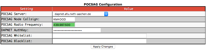
The Page will reload – now search for the „POCSAG Configuration“ section and fill out the needed values:
Node Callsign POCSAG – Enter the POCSAG node callsign.
Radio Frequency POCSAG – Enter the POCSAG radiofrequency. Per Andy Taylor in the Pi-Star User Forum : „If we get good buy-in from repeater keepers, we could have a really good paging network with great coverage, especially if we all use the same standard frequency.“ In Germany, where are already a lot of repeaters we use 439.987.500MHz, which will be the default entry in Pi*!
DAPNET AuthKey – Enter your authorization key for the Decentralized Amateur Paging Network. Which you got by Mail after you registered a New Transmitter as I told you on the Beginning of Configure Pi-Star and enable DAPNET
POCSAG Whitelist – This is a white list filter. You can enter RICs separated by a comma. Only calls to those RICs will be transmitted on the air. You can, for example, enter your own RIC here to only transmit calls to yourself. Beware that group calls, time sync messages and the like will be suppressed if you do not enter the corresponding RICs here as well.
Once you have done so you can send and receive messages/pages from the network. Please see the video below.
*Please keep in mind that this blog was created a few years back so this may well be easier now to set up. Enjoy! 73’s
hamadmin
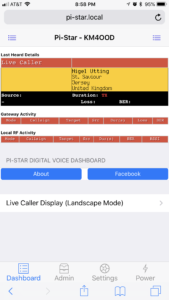
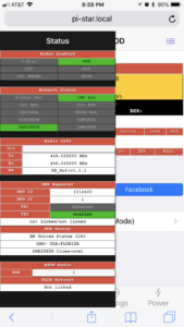
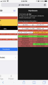
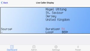
Adding a Mobile Dashboard for your Pi-Star Hotspot Device
I found a very good video that shows how to add a mobile dashboard to your Pi-Star Hotspot, this is very good for those that use their Hotspot while mobile either by connecting to your phone’s hotspot for an internet connection or purchase a Hotspot from Verizon or At&t. So let’s get started!
First, connect your Hotspot to your home/office network and open your browser of choice on your computer, then navigate to https://pi-star.local/admin/expert/ssh_access.php after this go ahead and log in with your credentials, the default credentials are “pi-star” as the username and “raspberry” as the password after this run the following commands.
Then after this has been completed, navigate to the “update” tab, this will take the RPI back to Read Only (RO)
Once this has completed you can navigate to the https://pi-star.local/mobile on your phone and access the Mobile Dashboard.
Right Menu
Left Menu
Landscape Mode
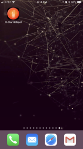
Taking it a step further for those with an iPhone:
1st Launch the Safari Browser
2nd Navigate to pi-star.local/mobile
3rd click on the Box with the up arrow icon
4rth on the bottom selection screens were you see Copy | Add to Reading List | Add Bookmark | Add to Favorites | Open in News, click on “add to Home Screen” edit the name of it and Voila! You have an icon on your home screen that you can open when you are mobile with your Pi-star device as I have mine in my car and you can check and make changes while mobile.
Credit goes to WOOTM for creating such good work!
DISCLAIMER: Install at your own risk! This addon is NOT supported by Andrew Taylor I have worked Andrew Taylor and following these instructions will not break the update process This addon does NOT require admin rights, so use at your own discretion.
hamadmin
APRS fun! iGate , Rapsberry Pi, RTLSDR and APRSC Servers
So…. after our Weather Balloon Presentation at the Wellington Radio Club, I decided I was going to check out my APRS Beacon setup that I have in my vehicle a Mini-Trak connected directly into my vehicles battery with a relay that will power off the unit after the engine turns off give or take about 5-10 seconds after. This allows me to track my vehicle and play with the data afterward. Well, it was time to dust off the device as I had not used it in a while. Last time I really used it was when I was on vacation and went to Puerto Rico and drove to the largest Radio Telescope there is.
This weekend I decided to check out how I can use my raspberry pi and my Custom Made RTLSDR as an iGate. I went online and found some information on Github as well as other sources. Some information worked some did not, especially the location beaconing, I ended up using UTM coordinates (Zone=17r easting=xxxxxx northing=xxxxxx). After getting this iGate finished and coded I had a Working iGate that captured all the radio transmissions on 144.390Mhz. After I got this going I left the project working on my office network rack, it consumes little to no bandwidth and power so why not leave it operational?!.
On Sunday I wondered what about the server this thing connects to? (ig) Well, I went and read a bit more for about 10 minutes and found the open source code for APRSC binaries. I went and created my own APRSC Server then went to take a nap and get ready for the hurricanes that are coming our way (Hurricane Irma). After this I went and sat in my office and did a bit more coding and linked up the server to their network and monitored it for a bit, I found that they are using bootstrap so I did some custom code to make it look better for my taste.
And thus concludes my APRS Weekend. If you are interested in seeing the iGate search for KM4OOD-10, for the Server you can navigate to my IO Webpage (Malave.io) and go to the APRSC.malave.io site this will show you the server and its glory. Now I will leave this running for about a month but because I am using an external server it will charge me 10$. I will make an image if I ever find a cheaper way to host this server, in the mean time it’s in the pool of servers. Enjoy!
• You can be a Rookie if you were first licensed in 2017, 2016 or 2015 – send the year you were first licensed in the exchange.
• Starting in April, if you were licensed before 2015 you can also be a Rookie if you made your first Amateur Radio contact during 2017, 2016 or 2015 or if you haven’t made any contacts on the contest mode (SSB, CW, or RTTY) before the Rookie Roundup contest, send the current year (2017) in your exchange – either of these reasons qualify you as a Rookie for just one year.
• Rookies will attempt to make as many contacts as possible during this 6-hour event. Rookies work everyone – and non-Rookies work only Rookies.
This is a great way to try out contesting in an event designed for newcomers. Hope to work you then! To pre-register teams or submit your score after the event, please visit the Rookie Roundup page hosted by Bruce Horn, WA7BNM.