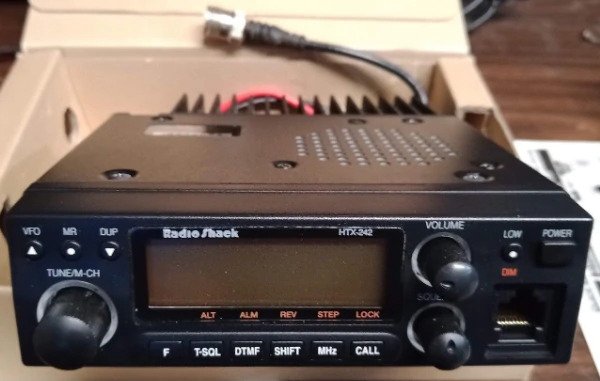
After a Ham Flea Market, I picked up this old 2M Radioshack Radio for 20$, I took it home and tested it and it works like a charm, I cleaned it up, the image above. Unfortunately, it suffers the same fate as any other of its kind and that was the coiled cable for the MIC it was chewed up and had electrical tape (vinyl tape) as well as some sections with small zip ties. Well, I couldn’t keep it in this form so this article focuses on the restoration of the microphone for this old radio.
Tools: Soldering Iron Heatgun or Rework Machine #2 Phillips screwdriver #0 Phillips Screwdriver Hot Glue Gun Cable Cutters Multimeter to test any two points for any shorts when soldering. * No other pin should show continuity.
Materials:
Small Zip Tie Solder Solder Flux Shrink Tubing Microphone 8 pin Cable ( Click me I am a link)
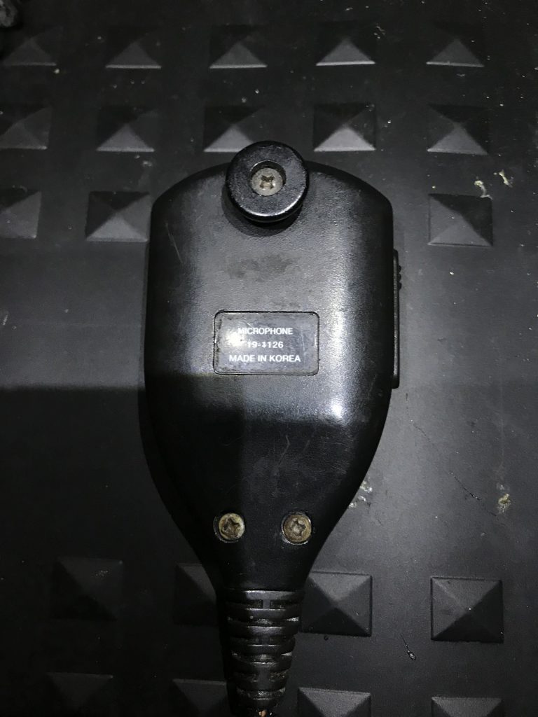
Step One: Remove the three screws on the rear of the MIC.
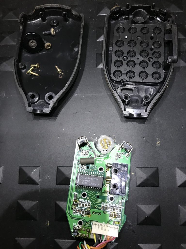
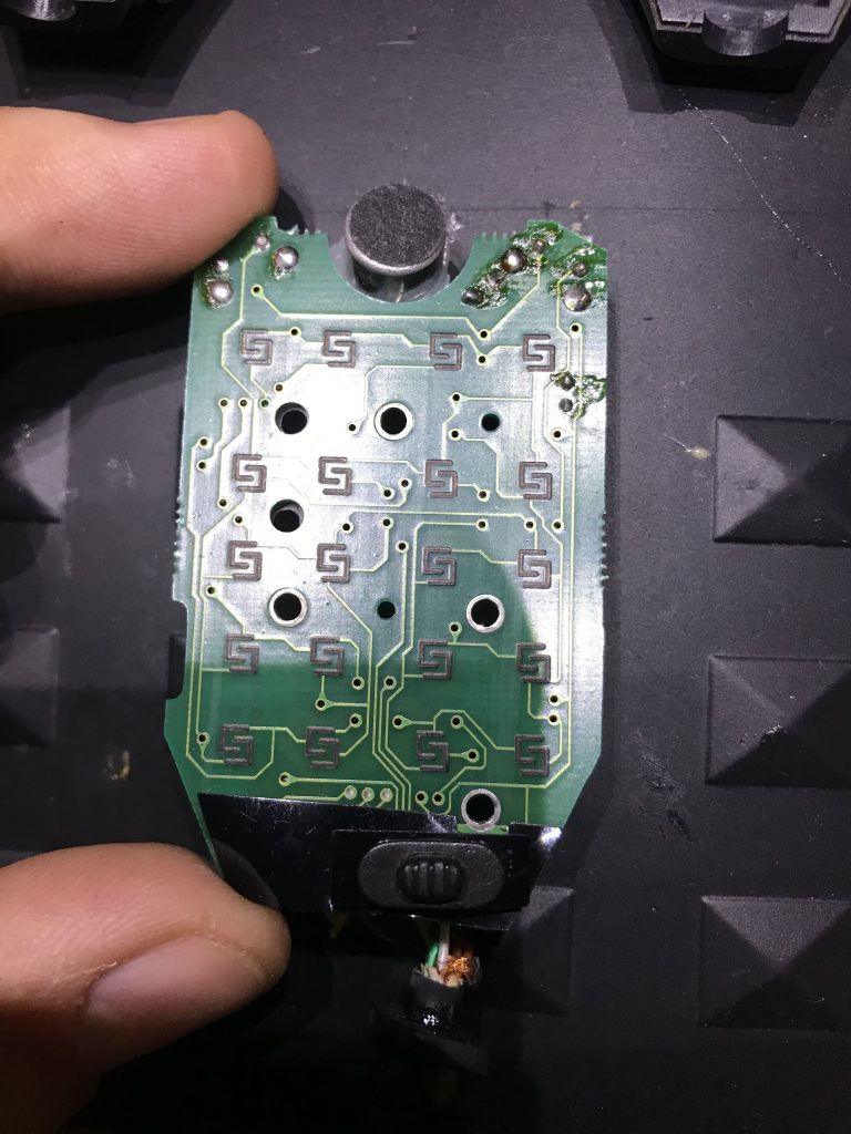
Step Two: Remove all 4 screws holding the PCB onto the MIC Case. Note* Take good caution for the buttons and surface mounted components.
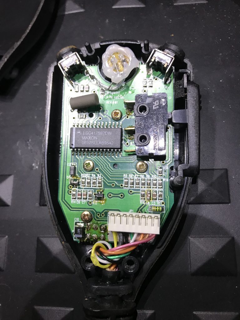
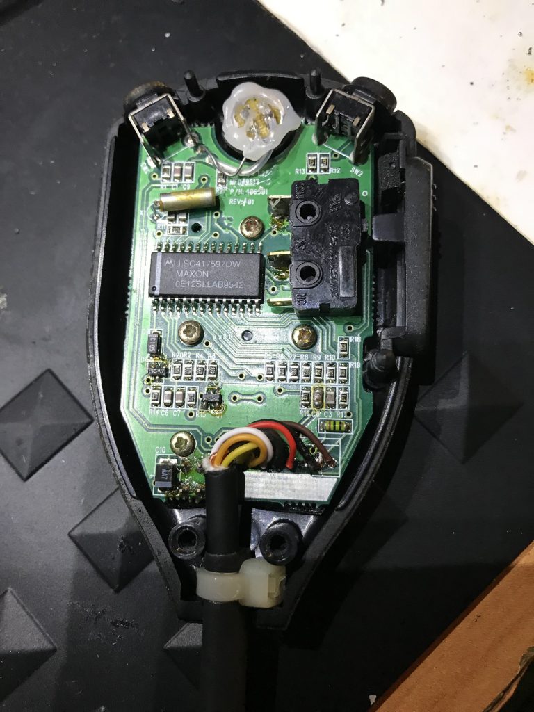
Step three: Remove the PCB from the Housing.
Step four: Remove the slider switch and the two small plastic slider covers with care.
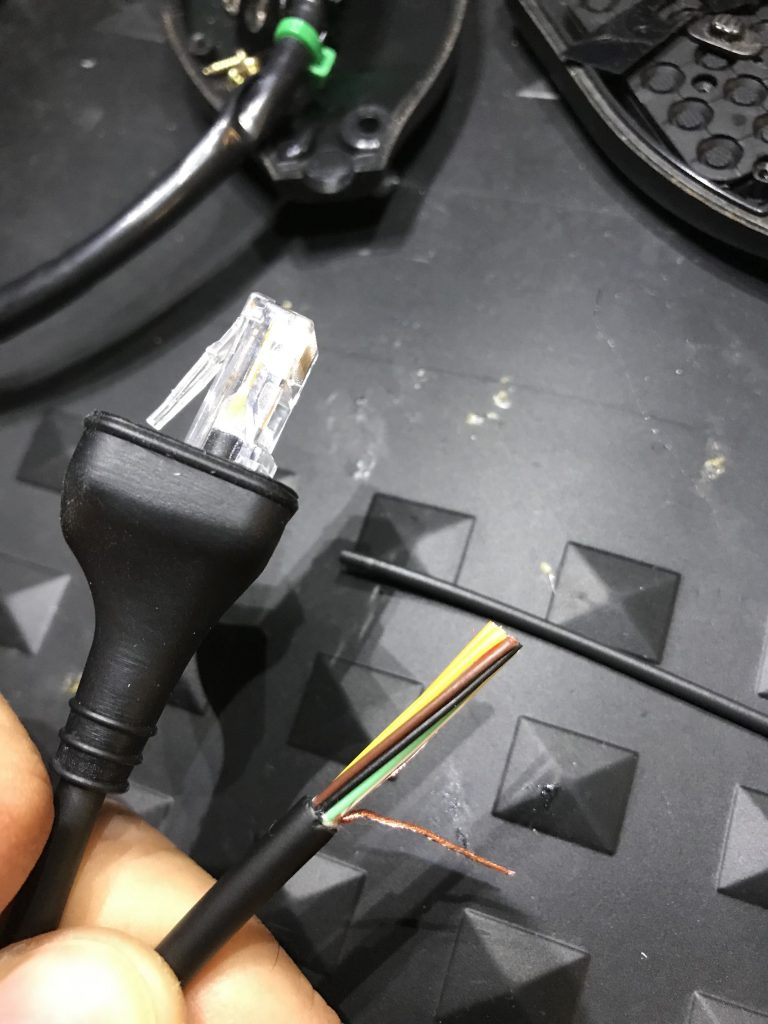
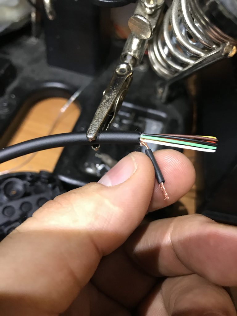
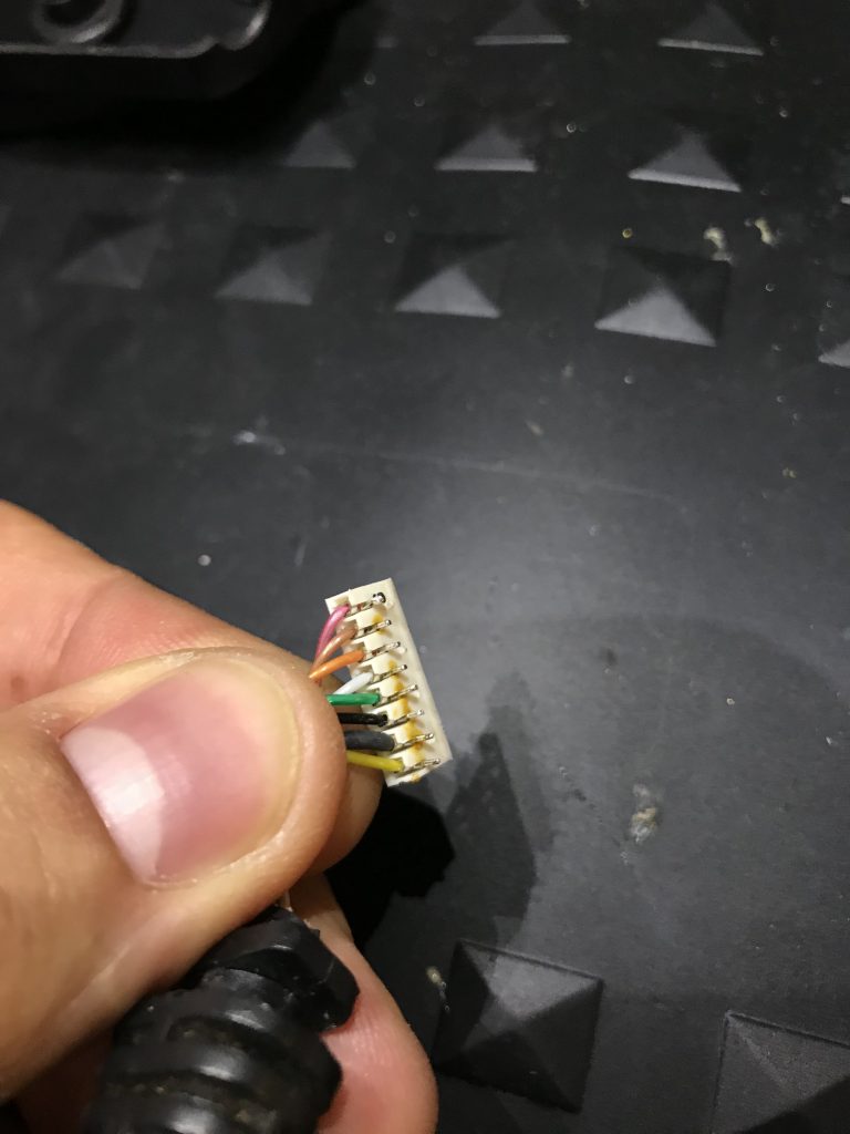
Step Five: Cut one end of the 8 Pin Coil cable and strip the ground then add a small shrink tube to protect it from shorting anything else. Also without heating up add some shrink tubing for later use as a strain relief on this end just push it to the side for later use.
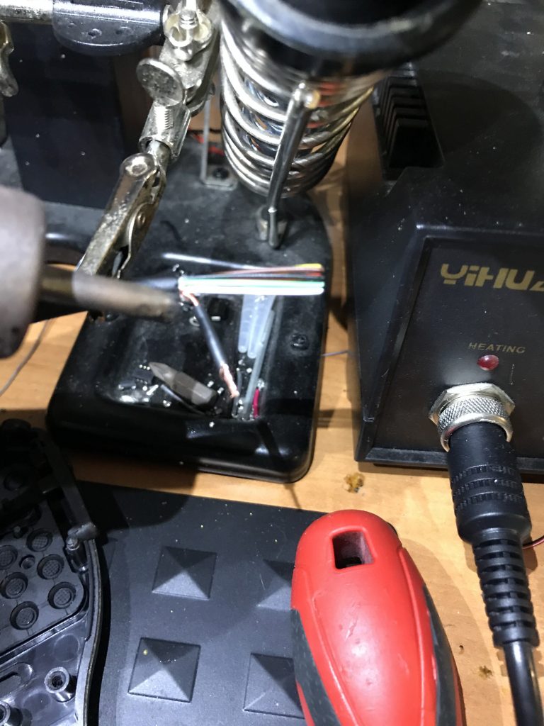
Step Six: Use a heat gun or in my case, I have a workstation so I used that at a low temp so as not to damage other conductors.
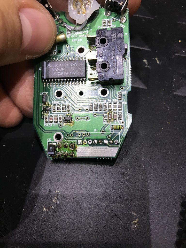
Step Seven: With caution remove the 8 pin header by applying solder flux and using a chisel tip then run the tip of the solder gun back and forth while applying some force. You will find that it will slowly come off the PCB board leaving no trace or marks. The key is to be patient.
Step eight: Clean the PCB with some Electronics Grade Isopropyl alcohol, a small bristle brush does not hurt 😉
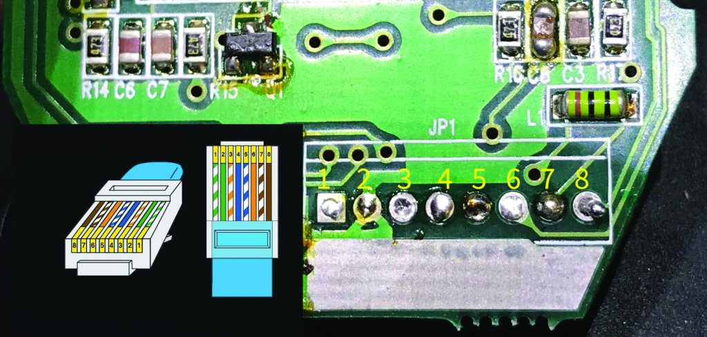
Step 9: This is the good part. Here you see the pins in relation to the 8 pin RJ45 Connector. Please disregard any color coding used by the manufacturer as I saw this not matching the factory MIC color code. Solder each of the conductors carefully and with patience, leaving at least 1″ of spacing for our “service loop”.
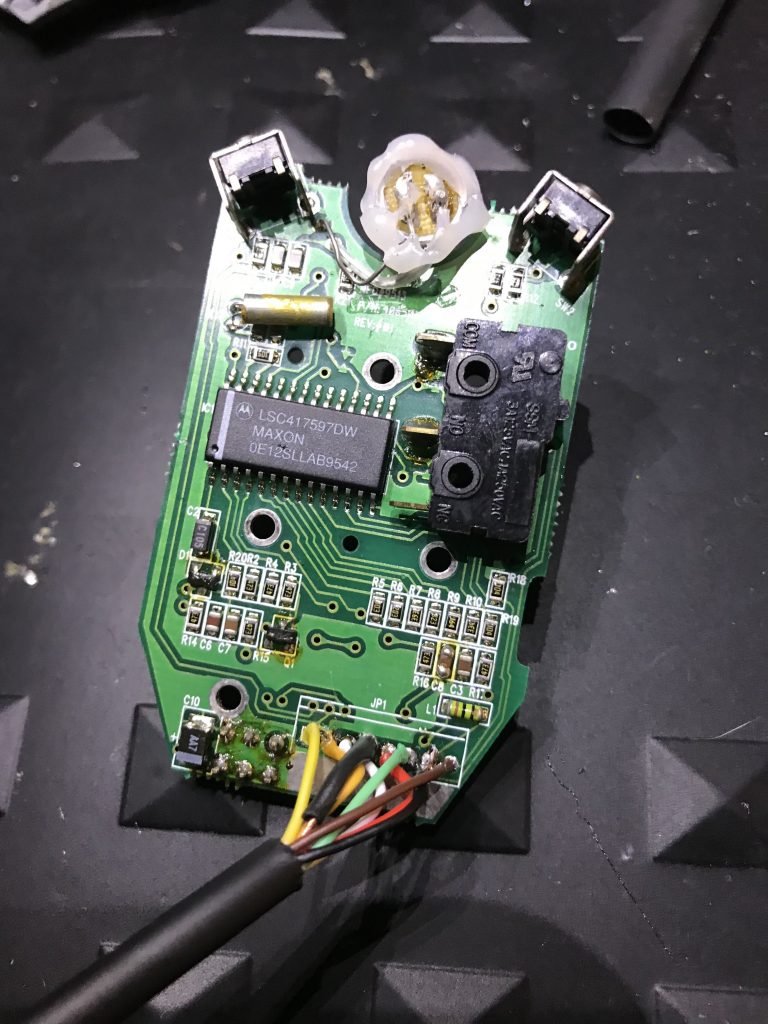
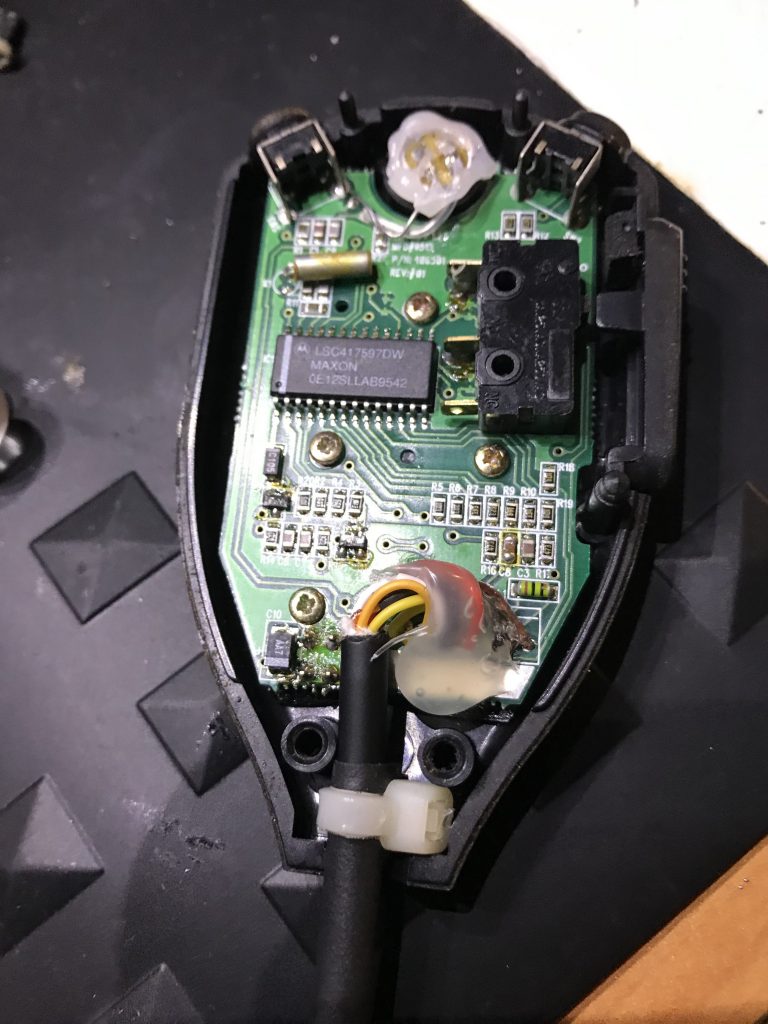
This is the image of the Soldering Completed.
Step ten: With care make your service loop add a small zip tie for strain relief, Here you can also see the shrink tubing added earlier in {step 5} for help with any strain as well.
Step 11: I added some hot glue to protect the joins from any movement wear.
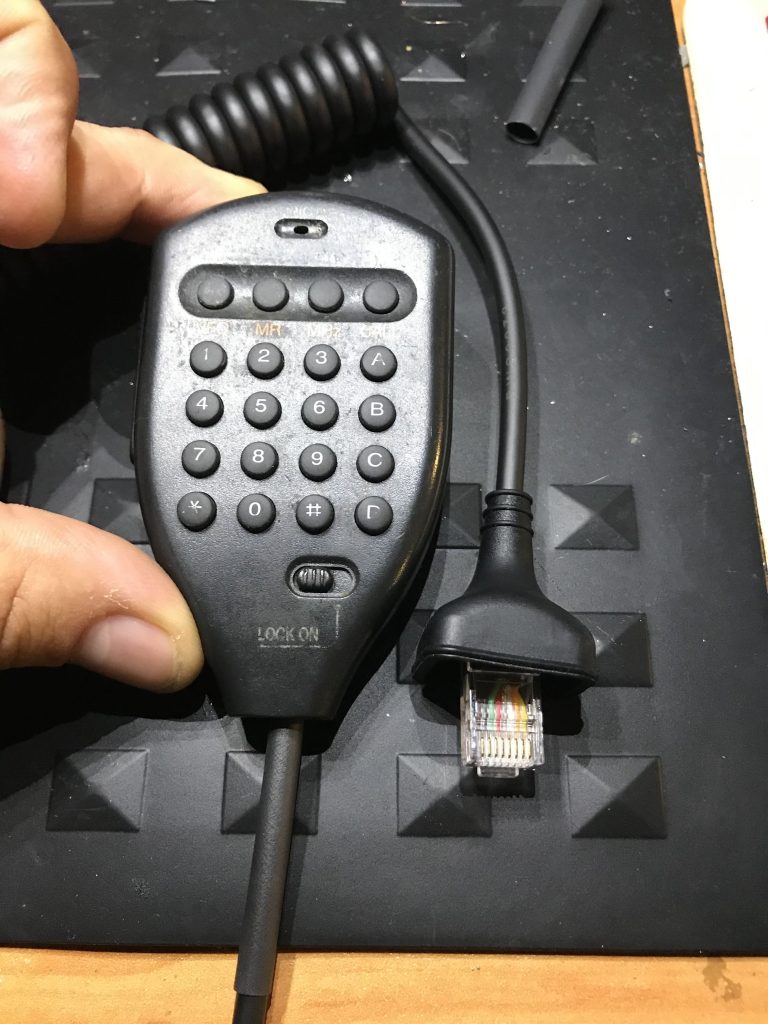
Put it all back together and here is the end product.