How to Manually Program a Baofeng Radio to a Repeater.

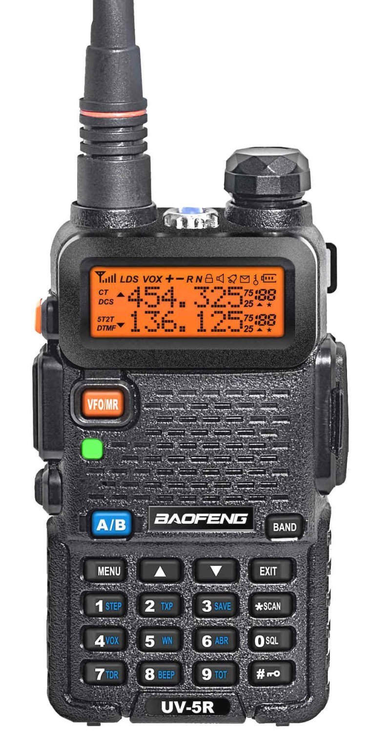
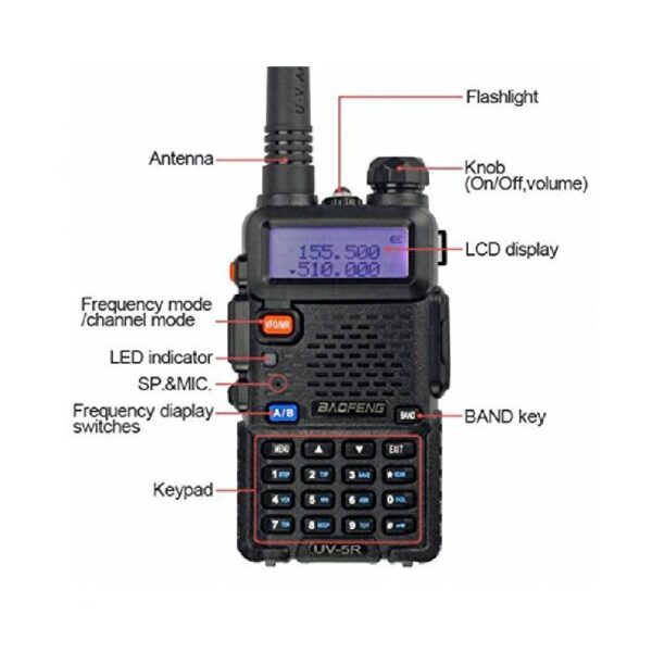
Programming a Baofeng handheld radio to a repeater can be a useful skill to have, especially if you are a radio enthusiast or are using the radio for emergency communication. In this article, we will go over the steps to program a Baofeng radio by hand, where to find the necessary information, and some tips to make the process as smooth as possible.

  1. Gather the necessary information:
  • The frequency, offset, and tone of the repeater you want to program into your Baofeng radio. This information can typically be found on the repeater’s website or through a local amateur radio club.
  • The model number of your Baofeng radio. This can be found on the back of the radio or in the user manual.
  1. Enter programming mode:
  • Turn off the radio.
  • Press and hold the “Menu” button while turning on the radio.
  • Release the “Menu” button when the display shows “Frequency Mode.”
  1. Input the repeater information:
  • Use the up and down arrow buttons to navigate to the desired memory channel.
  • Press the “Menu” button to enter the memory channel programming mode.
  • Use the up and down arrow buttons to navigate to the “RX Freq” field.
  • Enter the repeater frequency using the keypad.
  • Press the “Menu” button to move to the next field.
  • Use the up and down arrow buttons to navigate to the “Offset Freq” field.
  • Enter the repeater offset frequency using the keypad.
  • Press the “Menu” button to move to the next field.
  • Use the up and down arrow buttons to navigate to the “Tone” field.
  • Enter the repeater tone using the keypad.
  1. Save the repeater information:
  • Press the “Menu” button to exit the memory channel programming mode.
  • Use the up and down arrow buttons to navigate to the “Save” field.
  • Press the “Menu” button to save the repeater information to the memory channel.
  1. Test the repeater connection:
  • Turn off the radio and turn it back on.
  • Use the up and down arrow buttons to navigate to the memory channel with the repeater information.
  • Press the “Push-To-Talk” button and speak into the microphone to test the connection with the repeater.

Some additional tips for programming a Baofeng radio:

  • Make sure to double-check the repeater information before saving it to the memory channel to avoid any errors.
  • It may be helpful to write down the repeater information on a piece of paper or in a notebook to reference while programming the radio.
  • If you are having trouble programming the radio, try consulting the user manual or reaching out to a local amateur radio club for assistance.
  • Consider purchasing a programming cable and programming software to make the process of programming the radio easier and more efficient.

I hope this article has been helpful in explaining the steps to program a Baofeng radio to a repeater by hand. With a little bit of patience and attention to detail, you can easily program your Baofeng radio to connect to a repeater for enhanced communication.

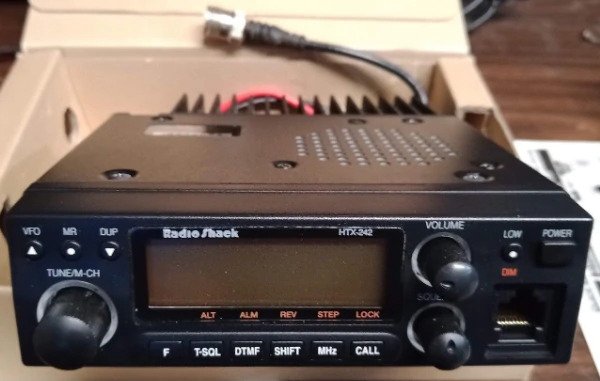
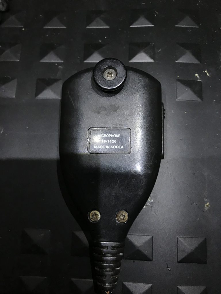
Radio Shack HTX-242 MIC Repair (MIC Part 19-1126)

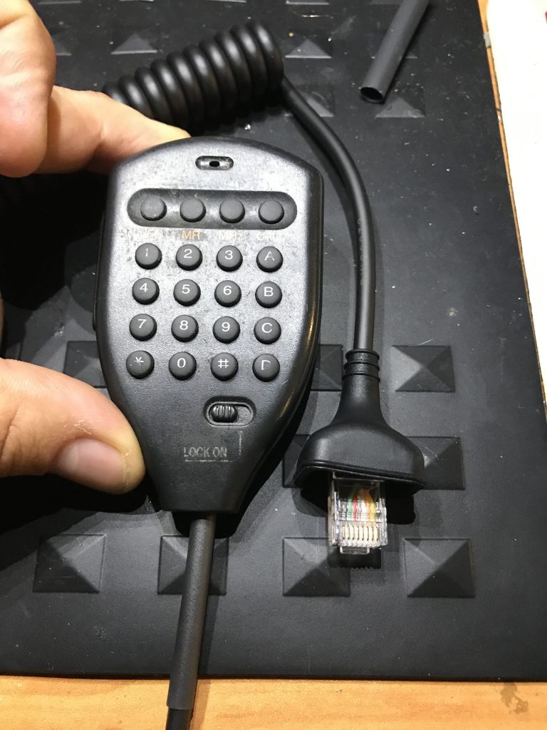
After a Ham Flea Market, I picked up this old 2M Radioshack Radio for 20$, I took it home and tested it and it works like a charm, I cleaned it up, the image above. Unfortunately, it suffers the same fate as any other of its kind and that was the coiled cable for the MIC it was chewed up and had electrical tape (vinyl tape) as well as some sections with small zip ties. Well, I couldn’t keep it in this form so this article focuses on the restoration of the microphone for this old radio.

Tools:
Soldering Iron
Heatgun or Rework Machine
#2 Phillips screwdriver
#0 Phillips Screwdriver
Hot Glue Gun
Cable Cutters
Multimeter to test any two points for any shorts when soldering.
* No other pin should show continuity.

Materials:

Small Zip Tie
Solder
Solder Flux
Shrink Tubing
Microphone 8 pin Cable ( Click me I am a link)

Step One: Remove the three screws on the rear of the MIC.
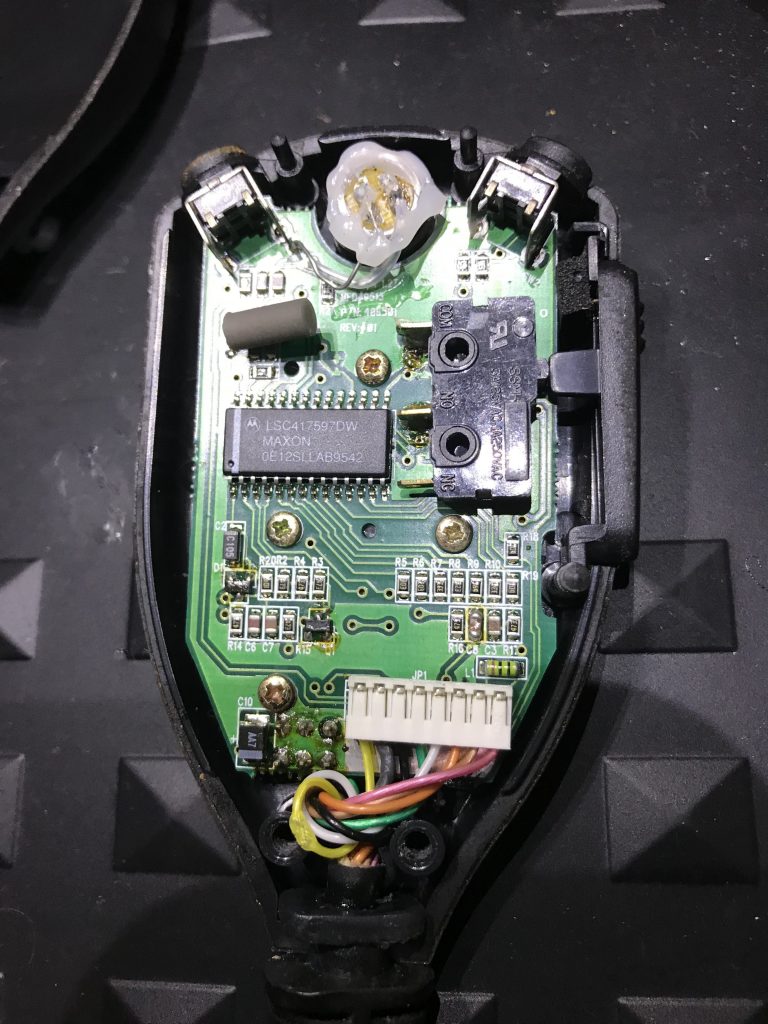
Step Two: Remove all 4 screws holding the PCB onto the MIC Case.
Note* Take good caution for the buttons and surface mounted components.
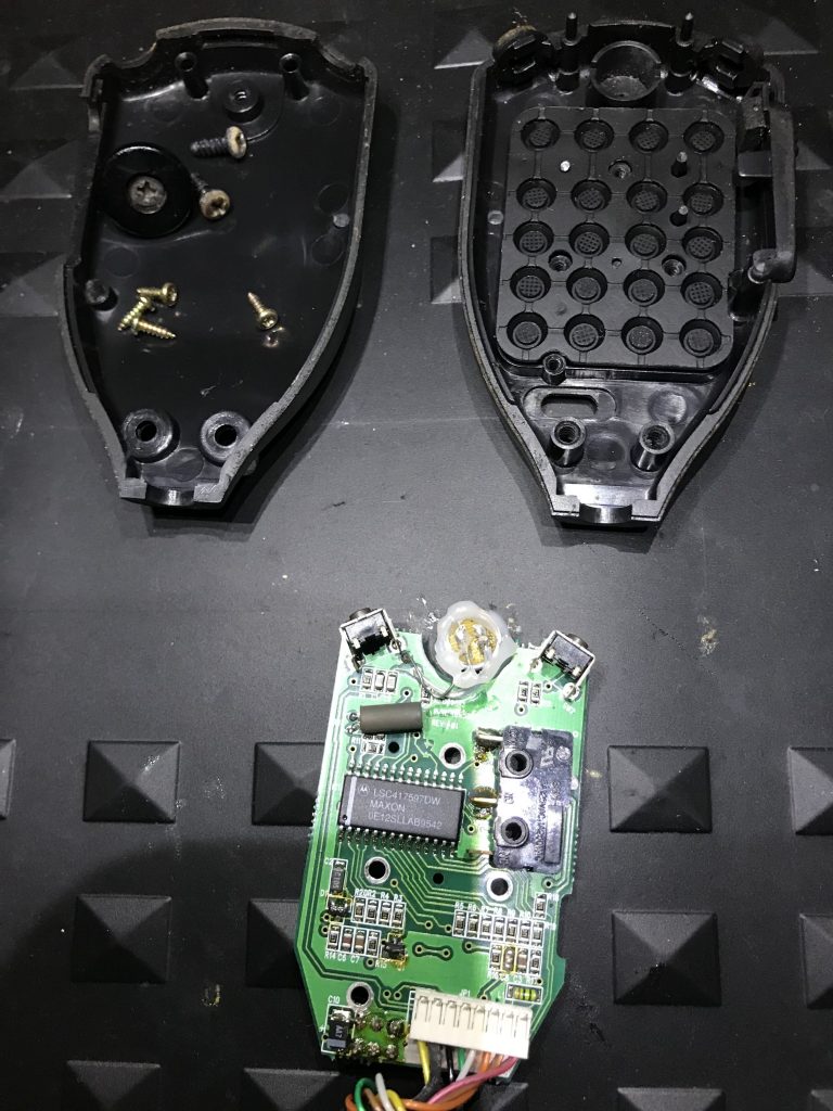
Step three: Remove the PCB from the Housing.
Step four: Remove the slider switch and the two small plastic slider covers with care.
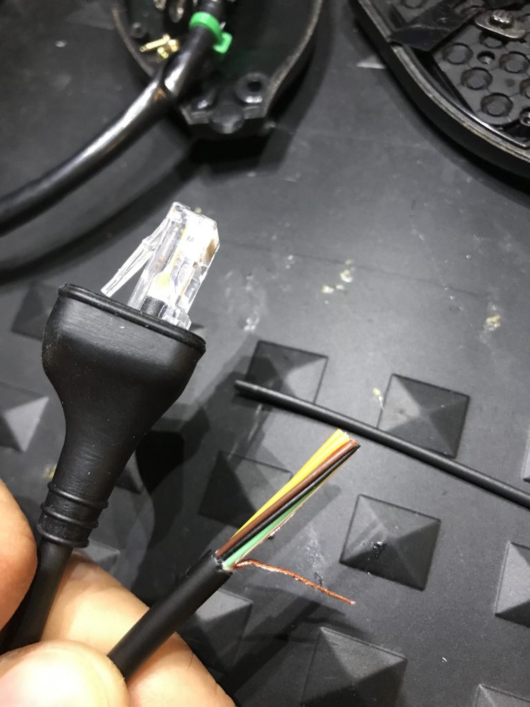
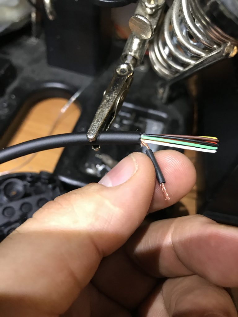
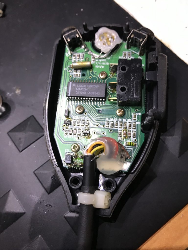
Step Five: Cut one end of the 8 Pin Coil cable and strip the ground then add a small shrink tube to protect it from shorting anything else. Also without heating up add some shrink tubing for later use as a strain relief on this end just push it to the side for later use.
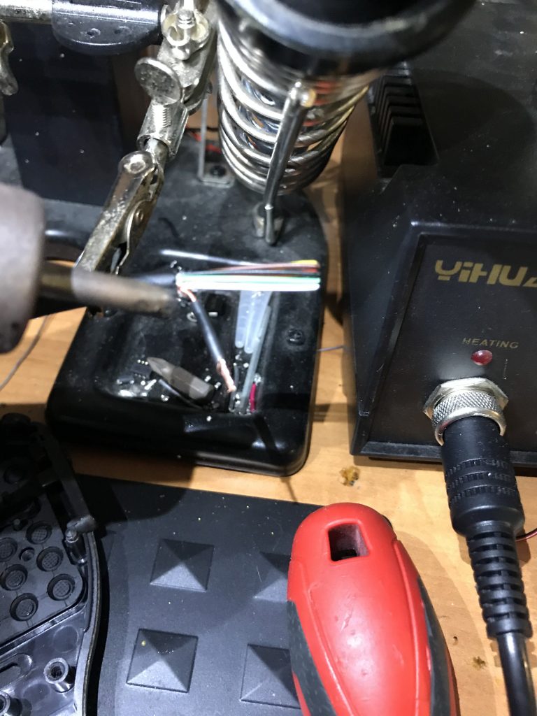
Step Six: Use a heat gun or in my case, I have a workstation so I used that at a low temp so as not to damage other conductors.
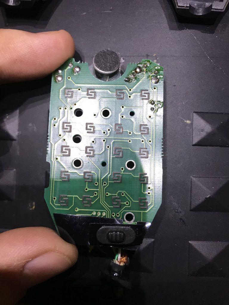
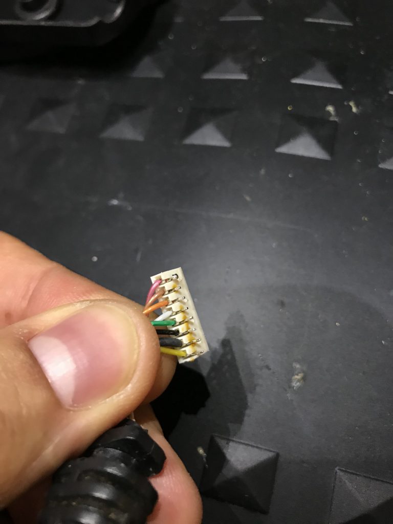
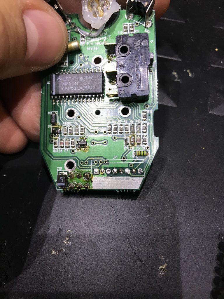
Step Seven: With caution remove the 8 pin header by applying solder flux and using a chisel tip then run the tip of the solder gun back and forth while applying some force. You will find that it will slowly come off the PCB board leaving no trace or marks. The key is to be patient.
Step eight: Clean the PCB with some Electronics Grade Isopropyl alcohol, a small bristle brush does not hurt 😉
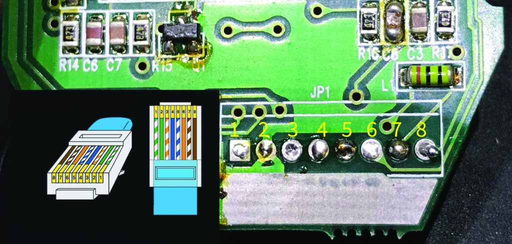
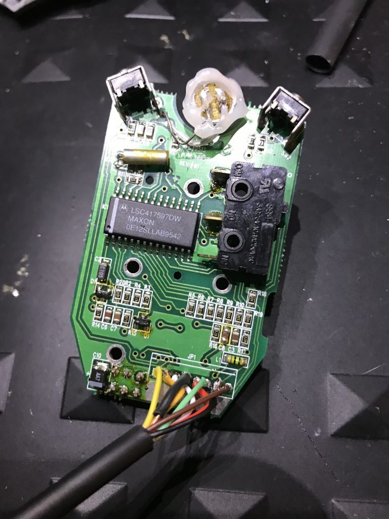
Step 9: This is the good part. Here you see the pins in relation to the 8 pin RJ45 Connector. Please disregard any color coding used by the manufacturer as I saw this not matching the factory MIC color code. Solder each of the conductors carefully and with patience, leaving at least 1″ of spacing for our “service loop”.
This is the image of the Soldering Completed.
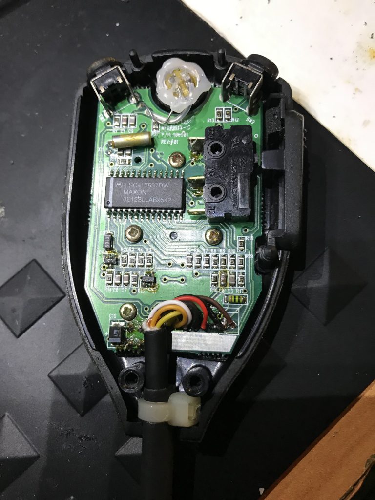
Step ten: With care make your service loop add a small zip tie for strain relief, Here you can also see the shrink tubing added earlier in {step 5} for help with any strain as well.
Step 11: I added some hot glue to protect the joins from any movement wear.
Put it all back together and here is the end product.
It works like a charm!

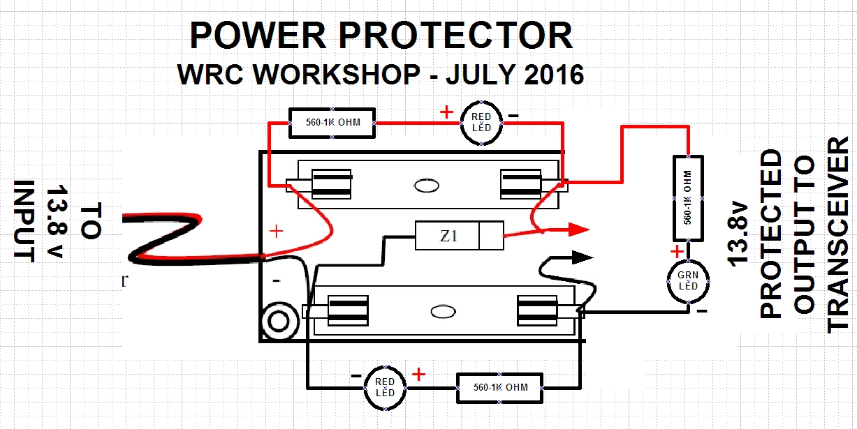
POWER CIRCUIT PROTECTOR WORKSHOP 7/16/2016

POWER PROTECTOR layout 3

Today we created a circuit that will protect your Ham Radio from any surges, just for about 5-8$ worth of parts.

Lets take a look at the items needed to complete this project.

  1. 3x LED’s (Red,Green,Yellow)
  2. 3x 560.1k OHM Resistors
  3. 1x Zener Diode (1.5KE15A)
  4. 30 Amp Glass tube fuses
  5. [ ́Fuseholder

After much deliberation, there was something about this circuit that was limiting my power output. I will be going over this circuit at a later date and find where it was limiting my amperage.

APRS fun! iGate , Rapsberry Pi, RTLSDR and APRSC Servers


So…. after our Weather Balloon Presentation at the Wellington Radio Club, I decided I was going to check out my APRS Beacon setup that I have in my vehicle a Mini-Trak connected directly into my vehicles battery with a relay that will power off the unit after the engine turns off give or take about 5-10 seconds after. This allows me to track my vehicle and play with the data afterward.  Well, it was time to dust off the device as I had not used it in a while. Last time I really used it was when I was on vacation and went to Puerto Rico and drove to the largest Radio Telescope there is.

This weekend I decided to check out how I can use my raspberry pi and my Custom Made RTLSDR as an iGate. I went online and found some information on Github as well as other sources. Some information worked some did not, especially the location beaconing, I ended up using UTM coordinates (Zone=17r easting=xxxxxx northing=xxxxxx). After getting this iGate finished and coded I had a Working iGate that captured all the radio transmissions on 144.390Mhz. After I got this going I left the project working on my office network rack, it consumes little to no bandwidth and power so why not leave it operational?!.

On Sunday I wondered what about the server this thing connects to? (ig) Well, I went and read a bit more for about 10 minutes and found the open source code for APRSC binaries. I went and created my own APRSC Server then went to take a nap and get ready for the hurricanes that are coming our way (Hurricane Irma). After this I went and sat in my office and did a bit more coding and linked up the server to their network and monitored it for a bit, I found that they are using bootstrap so I did some custom code to make it look better for my taste.

And thus concludes my APRS Weekend. If you are interested in seeing the iGate search for KM4OOD-10, for the Server you can navigate to my IO Webpage (Malave.io) and go to the APRSC.malave.io site this will show you the server and its glory. Now I will leave this running for about a month but because I am using an external server it will charge me 10$. I will make an image if I ever find a cheaper way to host this server, in the mean time it’s in the pool of servers. Enjoy!


Rookie Roundup

Coming up: 2017 April (SSB) Rookie Roundup!-

The next Rookie Roundup will be Sunday, April 16, using SSB.

NEW RULES – MORE ROOKIES!


• You can be a Rookie if you were first licensed in 2017, 2016 or 2015 – send the year you were first licensed in the exchange.


• Starting in April, if you were licensed before 2015 you can also be a Rookie if you made your first Amateur Radio contact during 2017, 2016 or 2015 or if you haven’t made any contacts on the contest mode (SSB, CW, or RTTY) before the Rookie Roundup contest, send the current year (2017) in your exchange – either of these reasons qualify you as a Rookie for just one year.


• Rookies will attempt to make as many contacts as possible during this 6-hour event. Rookies work everyone – and non-Rookies work only Rookies.


This is a great way to try out contesting in an event designed for newcomers.  Hope to work you then! To pre-register teams or submit your score after the event, please visit the Rookie Roundup page hosted by Bruce Horn, WA7BNM.


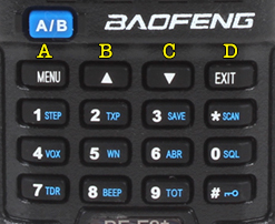
DTMF A,B,C,D” Where is it on my baofeng radio?


With Baofeng being a very popular and economical radio, a lot of Hams have this device and in some cases come across a means to input DMTF tones for either IRLP or Echolink. As you all know I am part of the Wellington Radio Club here in S. Florida and We have been adding new features to both of our repeaters. It came to my attention that one of the features that we are about to put in place uses a DTMF tone of  “#” which is being used for our Echolink node and Wires uses this as a default. We have changed this to A and B for our Echolink and IRLP Nodes since we have multiple ones in one repeater. I found that my simple radio did not have this but my friends Yaesu did have these letters (A, B, C&D) printed on the keypad. Well here is the simple solution. See image bellow. The radio will output these but it seems that Baofeng did not quite have room to add the letters to their HT. Seems like a simple thing but when you are out and about trying to access a feature on your favorite repeater and the repeater has prefixes it can be a headache.


Menu = A   ▲ = B   ▼ = C   EXIT = D


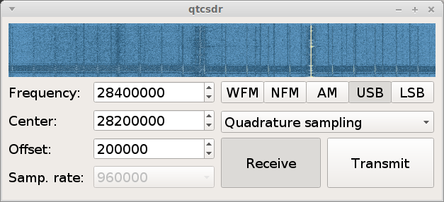
QSTCSDR – Creating your own Tranciever with a Raspberry Pi 2 or 3 and a RTL-SDR Dongle

qtcwsdr


After updating the post were I was using the RPI and a RTL-SDR dongle to create a Server for those that wanted to listen to the WRC Repeater, I stumbled upon the blog of the creator of OPENWEBRX and found a nifty article and library that allows you to use an RTL-SDR and a RPI as a transceiver, here is the github repo.


Lets get started, you will need an RPI 2 or 3 and an RTL-SDR Dongle after imaging your SD card with a copy of Debian Jessie set the RPI to overclock “medium” of course you must have some kind of cooling for the chips, amazon has RPI Heat sinks for sale that you can use. After this go right ahead and from within the home run the following code.


sudo apt-get update && sudo apt-get upgrade && reboot

This will update and upgrade your RPI.

Once it has been updated we can move onto adding the software needed. Run the following commands one by one , adding a “Y” for yes every time the Pi asks for more disk space.


git clone https://github.com/ha7ilm/qtcsdr
cd qtcsdr
./rpi-install.sh
./rpi-test.sh

If you run into trouble and need to do some troubleshooting go ahead and reference the well written Github repo

Credit of course goes to ha7ilm for his contributions towards the SDR community.


………… I almost forgot after installing it and you need to run it once more go ahead and cd into the qtcsdr directory then run the shell script ./rpi-test.sh  ENJOY!

Also this is done via SSH, if you are in windows you can use  PUTTY and if you are in Mac OSX or Linux simply run the Terminal.


1249400

Cheap Signal Link Style Interface!


Signal Link

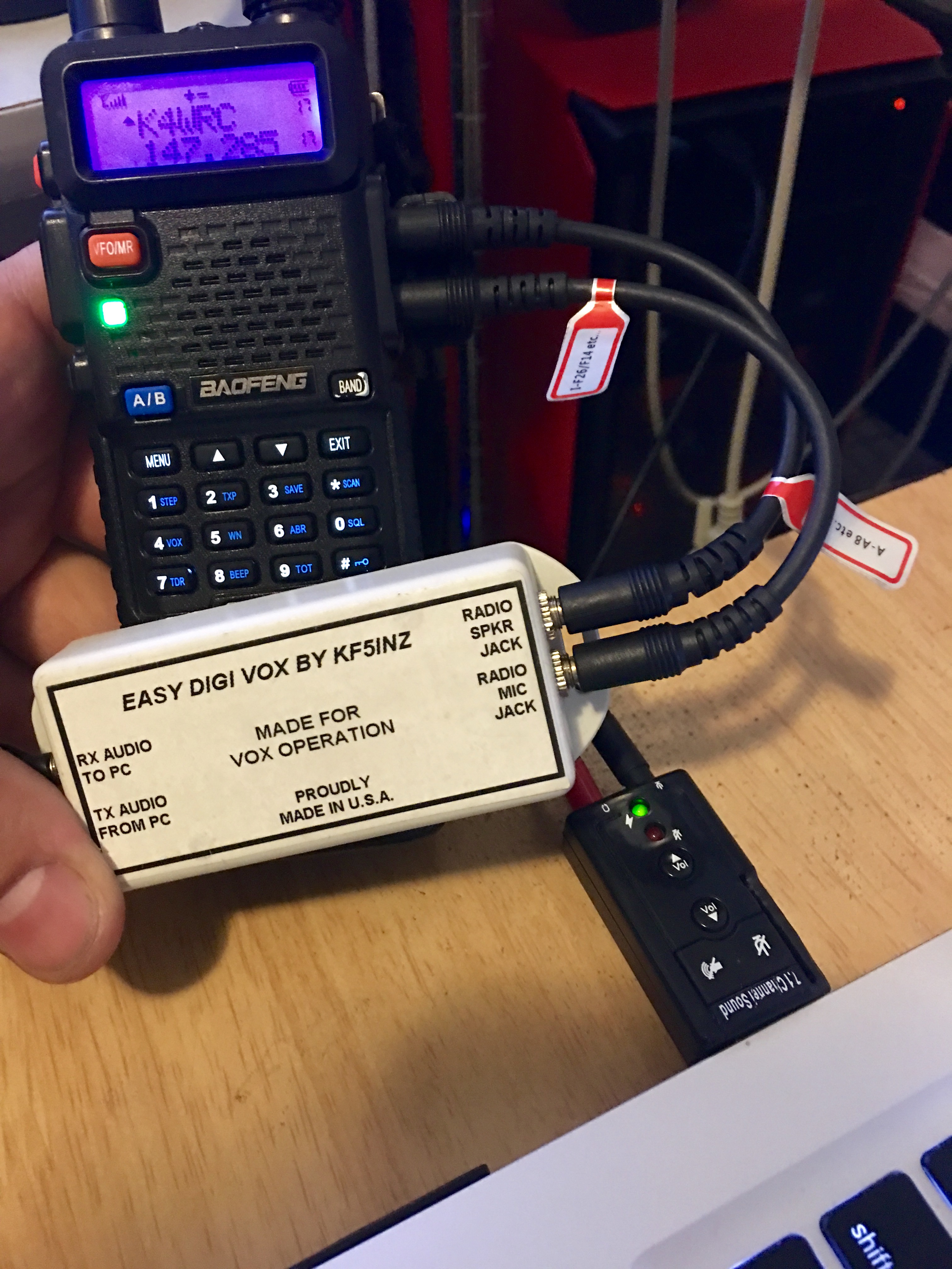
We all know that Hams often are cheap when purchasing hardware. There are some modes that I personally would like to master and these would be SSTV and MBEMS ( MT632KL) as well as others. But we all are on a budget and today I was part of the Wellington Radio Club Slow Scan Net. I was having some issues while transmitting using acoustical coupling, I also got some RF burn from my Baofeng’s Battery terminals, not good at all. So I decided enough was enough and I wend to my Home lab to gather the items that I needed to create my own “SignalLink”.

Here is what you will need to accomplish this.

  • HT (Wouxun, Baofeng or Kenwood) Others may work , you will need to ensure the size of the MIC and SPKR output.
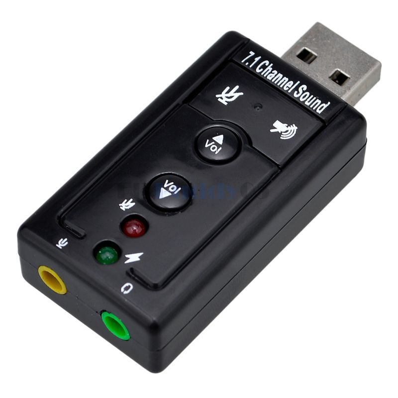
  • baofeng UV5R1x Sound card :  found on Ebay (LINK)
    Price: US $3.99

s-l1600

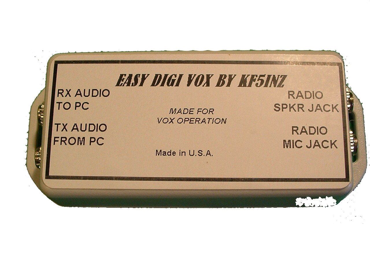
  • 1x “EASY DIGI” Digital Sound Card Interface by KF5INZ : found on Ebay (LINK)
    Price: US $22.95

digivox

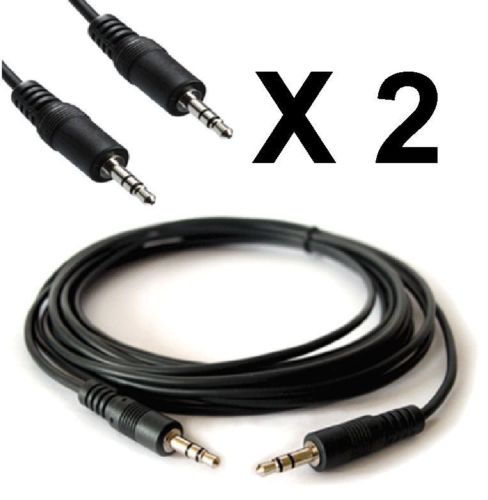
  • 2x 3.5mm Audio Cables (AUX Cables) : found on Ebay (LINK)
    Price: US $4.95

2x 3.5mm cables

  • 1x 3.5mm Male to 2.5mm Female Audio Adapter Converter : found on Ebay (LINK)
    Price: US $2.59


A total of $34.48 US. The Signal Link is $120.00 US plus shipping. I have successfully tested it on SSTV and MBEMS, both working great!

FullSizeRender

I have tested it on MAC OSX as well as Windows 7,8,8.1 and W10 as well as VMWare. Hope you guys find this useful for those looking to send and receive data via your HT. 73’s


Instructions on how to connect your HT using this method will be completed this week… Stay Tuned…..


socheep

Orlando 2016 – HAM FEST

Orlando 70th logo


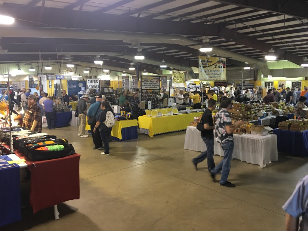
This was my first time at a Ham Fest, let me tell you it was a great day, although my legs hurt from walking all day it was well worthing it. I will summarize my day enjoying this hobby.


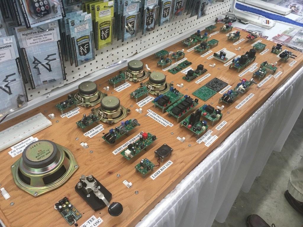
I first started with going into the Commercial area where there was some trinkets here and there , got a SATA HDD Adapter as well as an audio card for spares.

I saw some small Arduino and electronics parts booth but I did not need anything from them.

IMG_0638


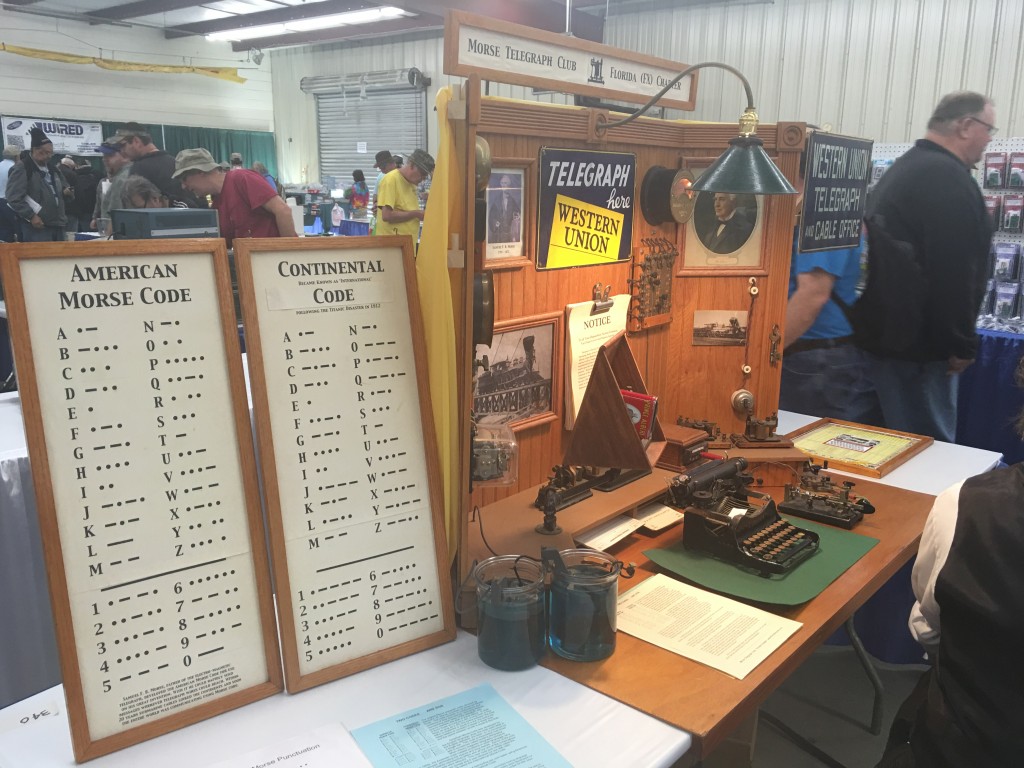
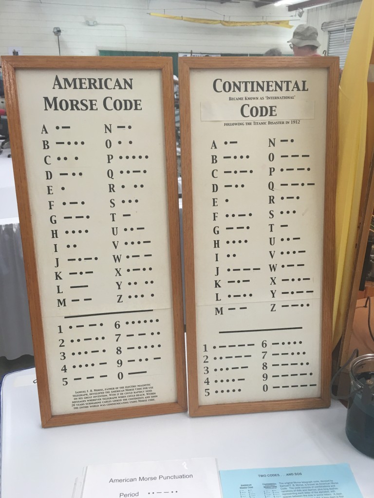
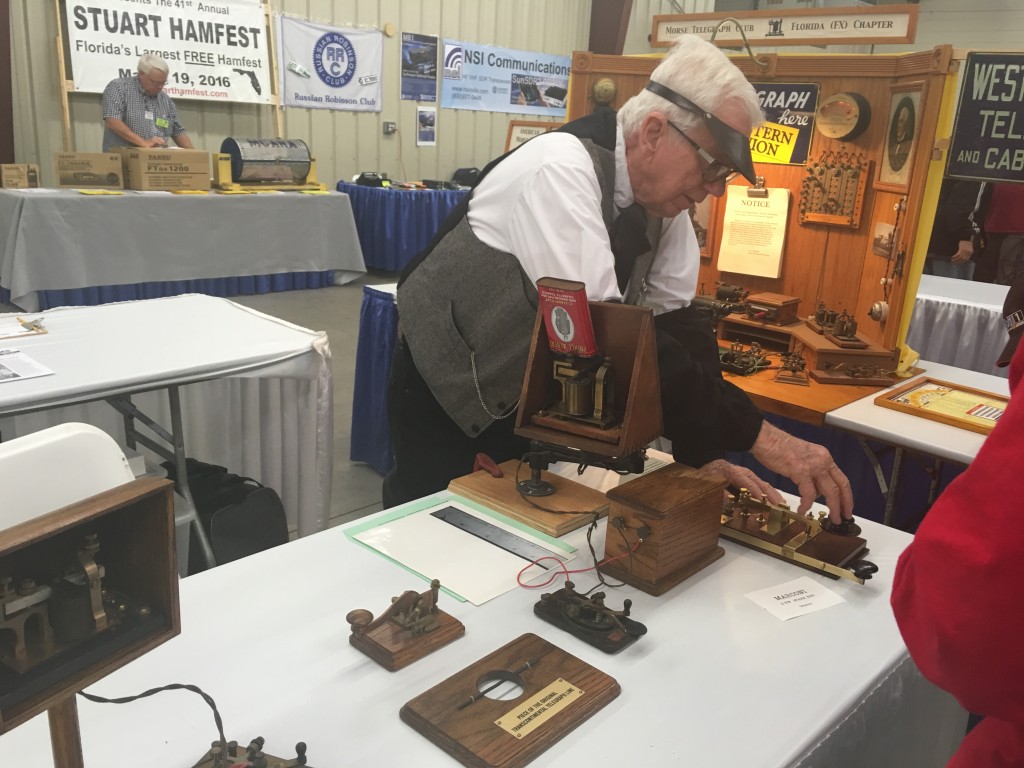
I was going from booth to booth until I found myself in front of a Telegraph booth.

IMG_0643

IMG_0644

IMG_0640

IMG_0668

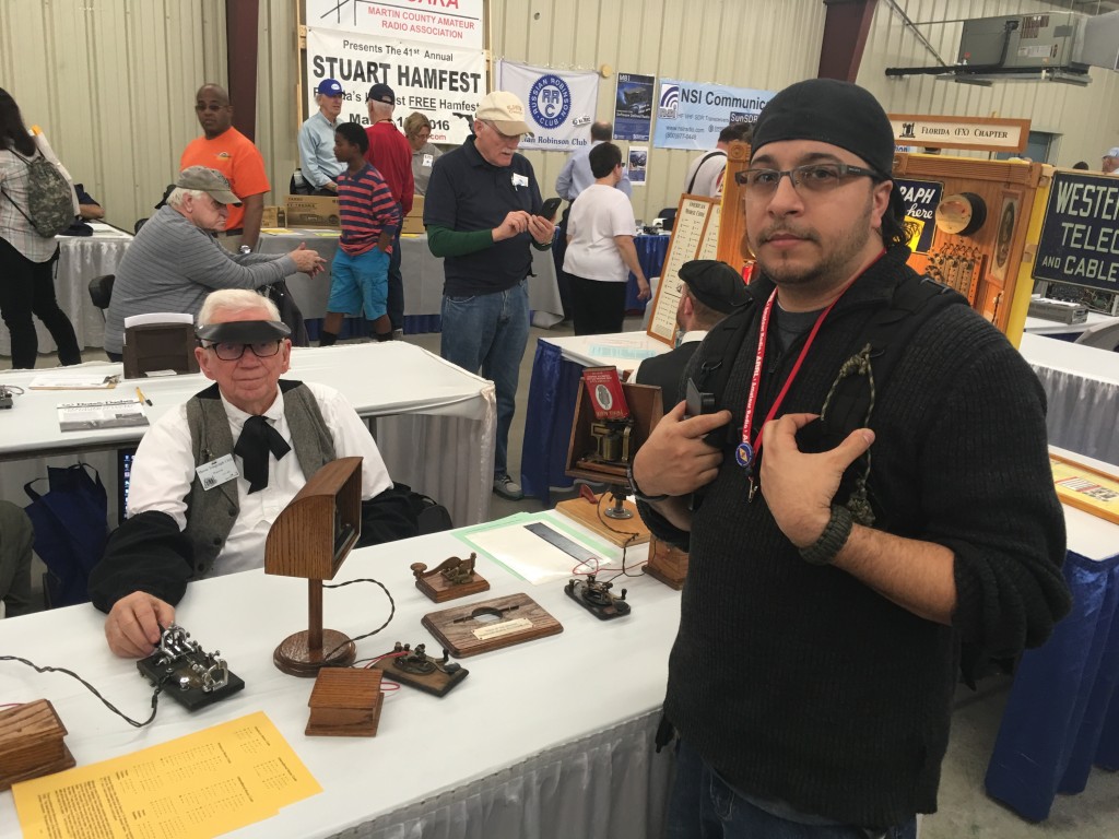
The telegraph machine caught my eye although I have seen these before online, the guys at the booth where very knowledgeable, spoke with them for about 20 minutes. The Morse Code is not necessary nowadays to become a Ham, I would love to learn it.


At the Ham Fest they had many people with new items to used items as well as educational booths. SDR was the Popular Booth with Demos.


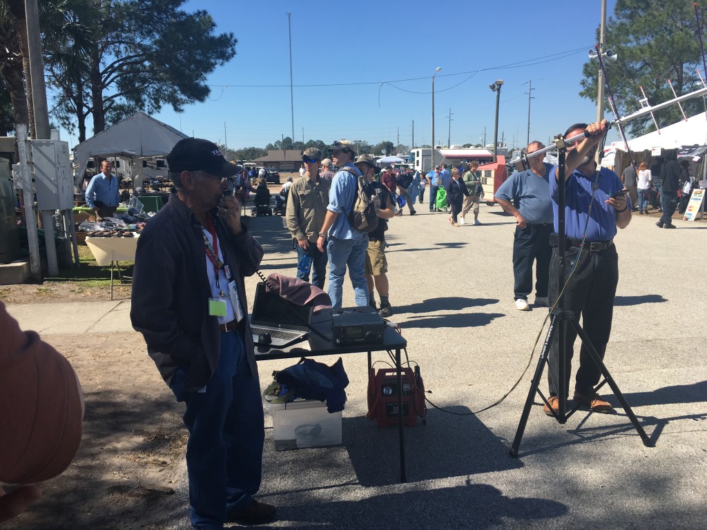
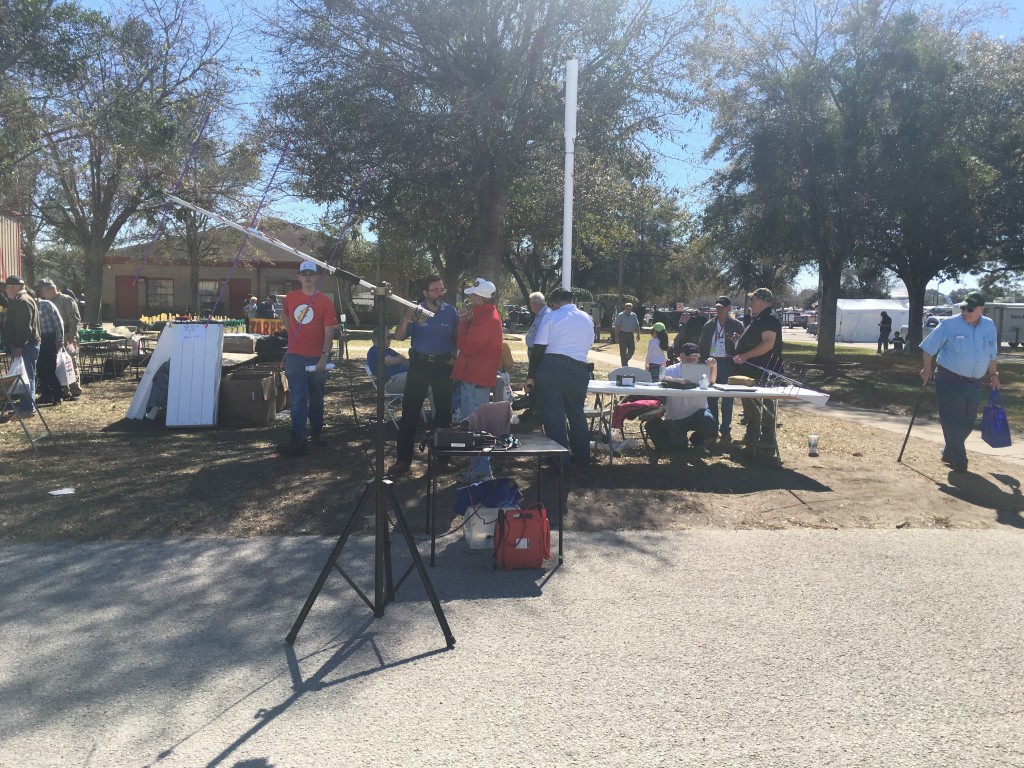
There was also the Satellite from HAMSAT doing a Demo with both an Arrow Antenna and a n SDR and its SAT Antennae.

Here you can see them setting up the Software as well as using a simple 20$ Nooelec SDR Dongle to pick up the incoming signals from the Satellites Orbiting the Earth.


Simple test before the real Demo.


The Demo 😉

IMG_0650

IMG_0661


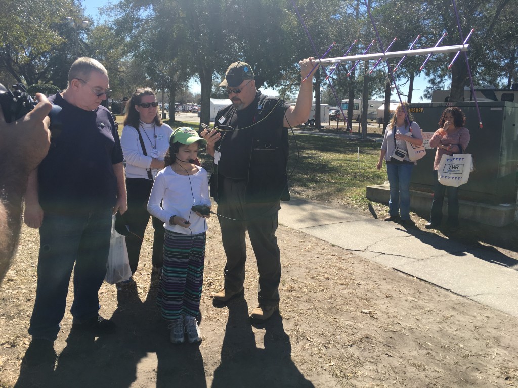
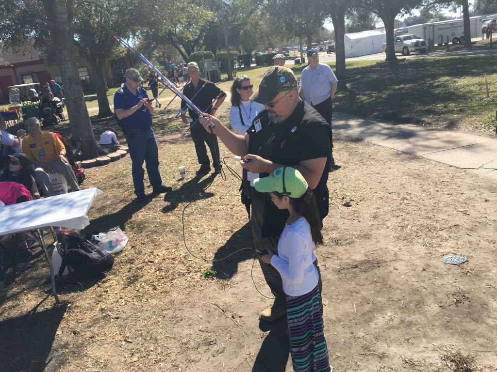
After this I went to other booths but not before getting information that a 9 Year old Gild would be doing a Demo and working the satellites herself.

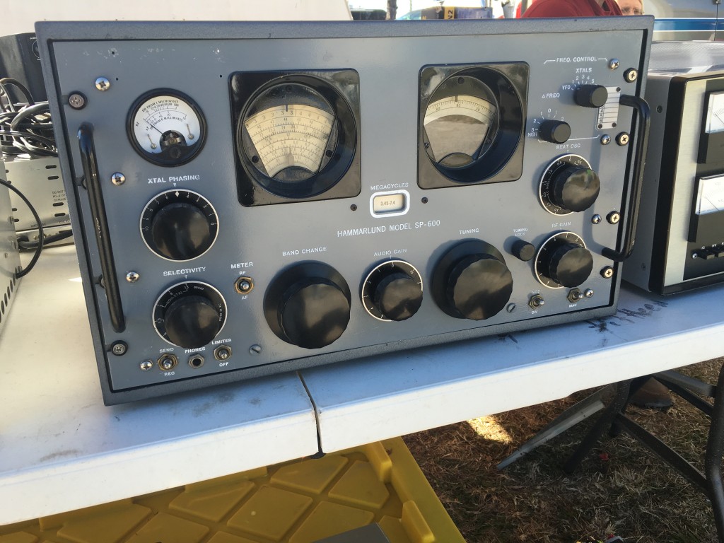
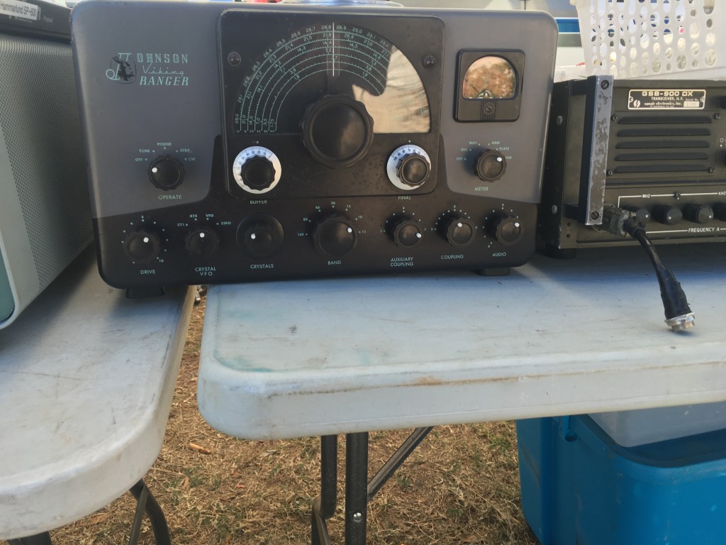
Random interesting items:


IMG_0685

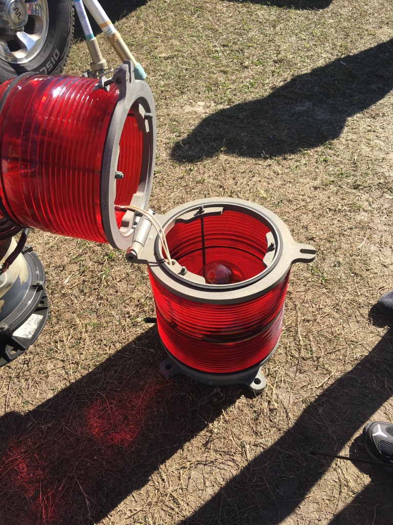
Tower Light

IMG_0687

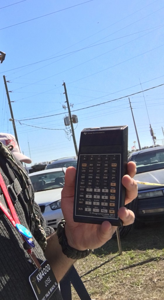
Only a Geek would be fascinated by this old Texas Instruments Calculator. It had the Library on a chip, it was that old.


IMG_0678

IMG_0680

IMG_0682

IMG_0646

IMG_0662

IMG_0663


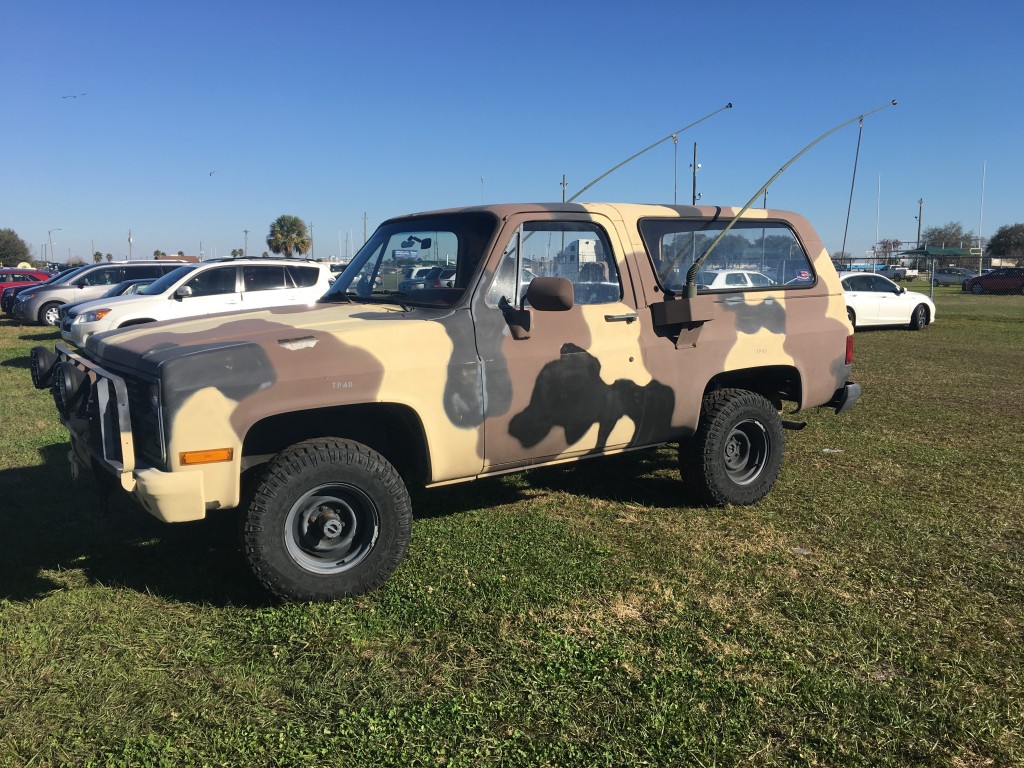
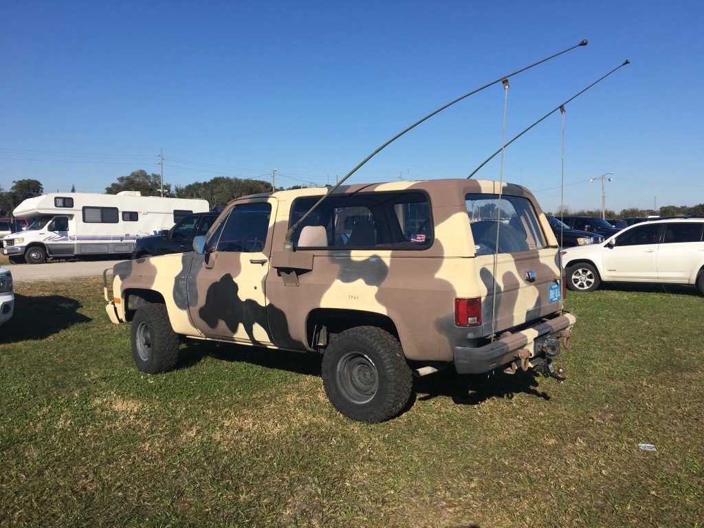
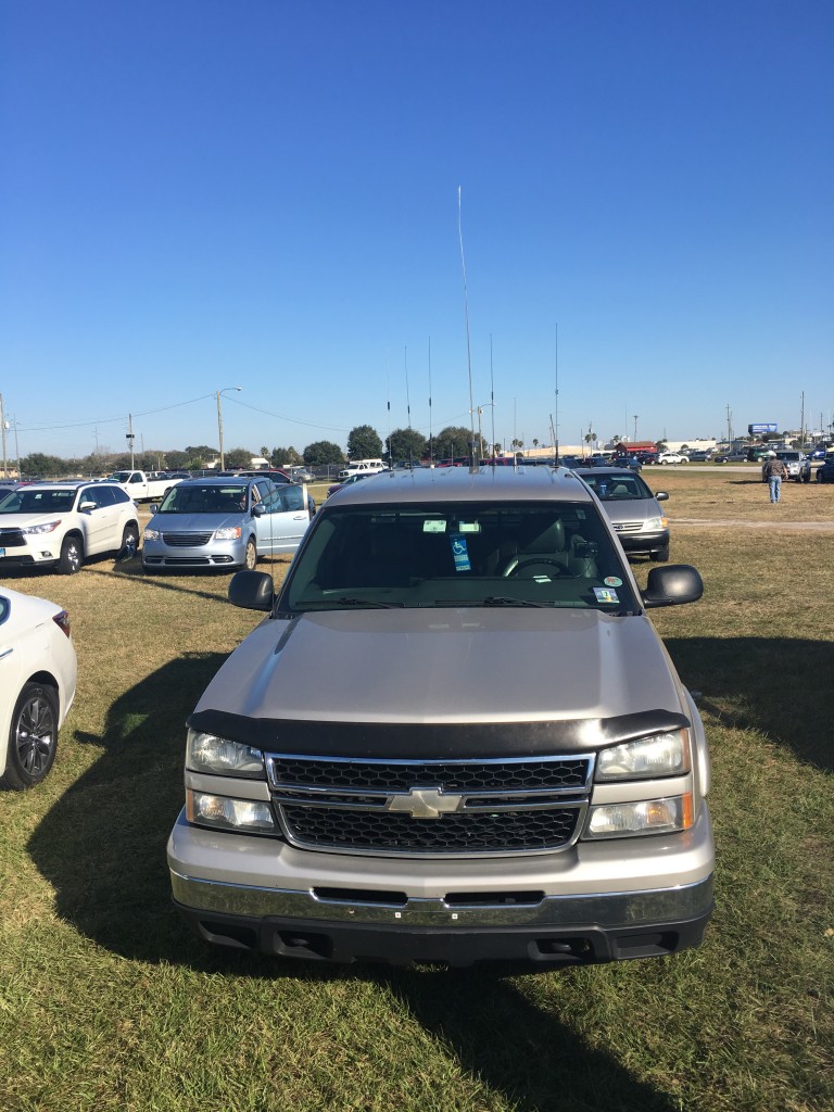
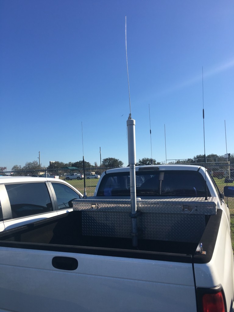
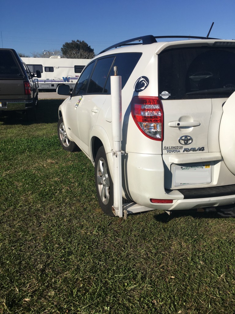
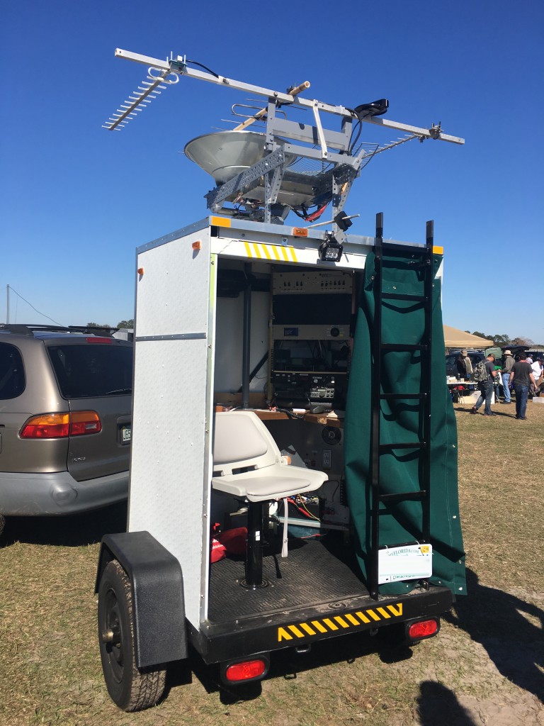
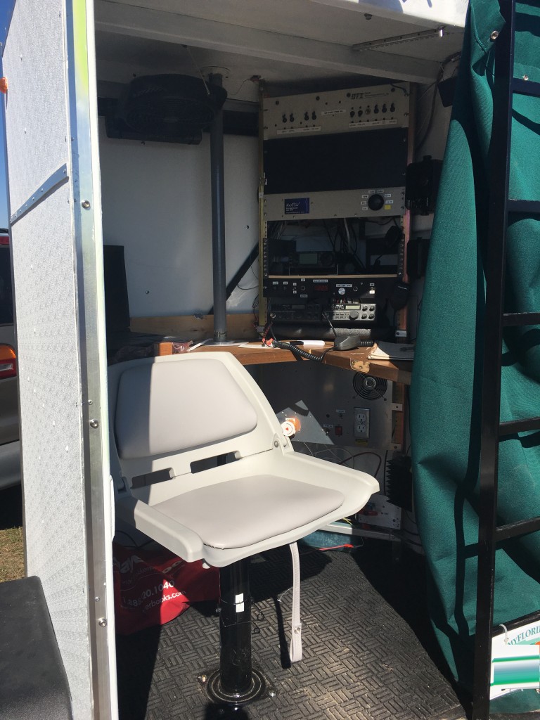
Interesting Vehicle/Rigs.


IMG_0693

IMG_0694

IMG_0690

IMG_0696

IMG_0695

IMG_0683

IMG_0684


And of course the highlight of the day the 9 Year old which I believe her name is Hope, working the satellites with what I believe to be her father.

IMG_0672

IMG_0676


IMG_0659


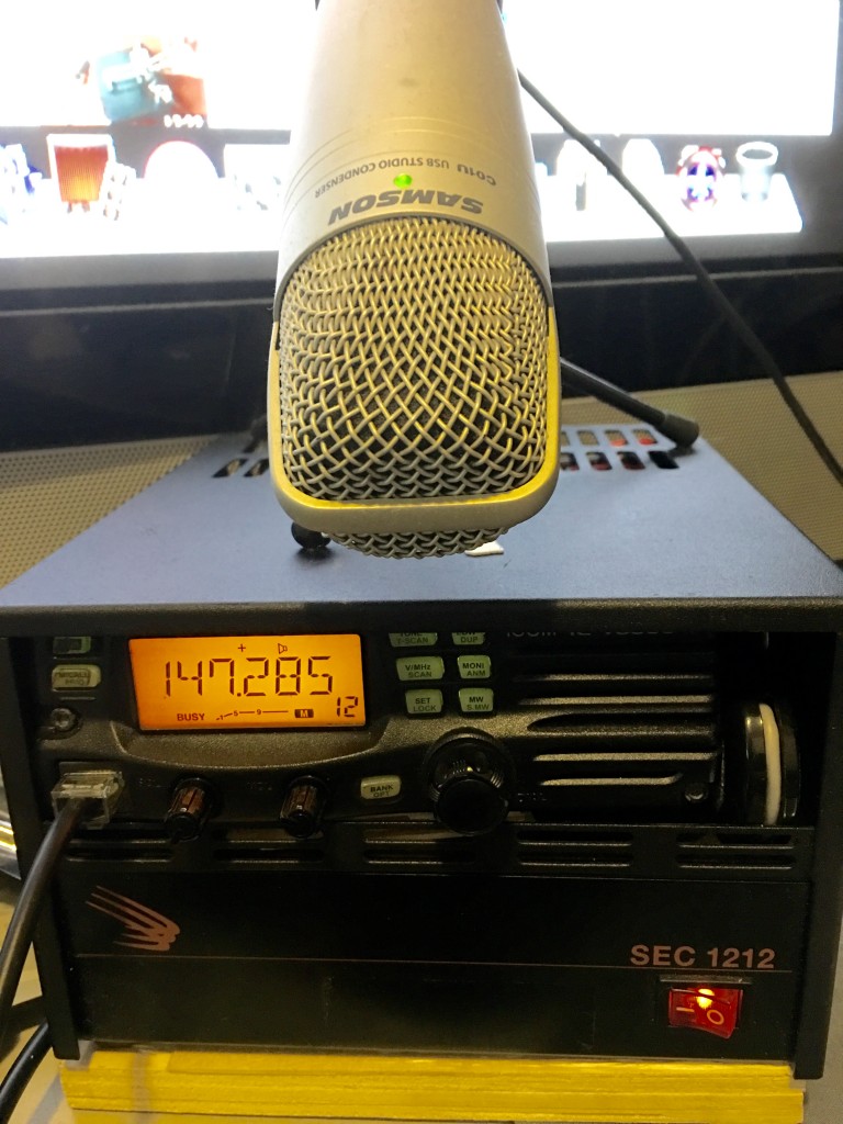
Items I picked up there where a few small electronics a Baofeng Radio and a used Base with an SEC 1212.


FullSizeRender

After all day Geeking out it was time to go. I would like to thank everyone, Specially Chris and Larry for giving me the opportunity to enjoy this.

PS. Next year I will bring a dedicated camera to take more pictures and Interview people.

73’s ;P


Creating a Web SDR with OpenWebRX and a 7-20$ SDR Dongle.

owxs-logo-big


For this you must have a Linux box or simply have a raspberry pi 2 running debian or other linux distros of choice. In this example we are going to focus on getting the device on your home network later we can talk how you will share this or post it onto your domain.
 

Items needed:

We first need to install some dependencies for this we will run this command on terminal


sudo apt-get install build-essential git libfftw3-dev cmake libusb-1.0-0-dev

Requesting the build rtl-sdr from github
git clone git://git.osmocom.org/rtl-sdr.git

cd rtl-sdr/


mkdir build


cd build


cmake ../ -DINSTALL_UDEV_RULES=ON


make


sudo make install


sudo ldconfig


cd ../..
We need to disable the DVB-T driver, which will prevent the rtl_sdr software from accessing the stick
Note that if you want to use it for DVB-T reception later, you should undo this.

sudo bash -c 'echo -e "\n# for RTL-SDR:\nblacklist dvb_usb_rtl28xxu\n" >> /etc/modprobe.d/blacklist.conf'


sudo rmmod dvb_usb_rtl28xxu # disable that kernel module for the current session

Lets download OpenWebRX and libcsdr (subdirectories will be created under the current directory).

git clone https://github.com/simonyiszk/openwebrx.git


git clone https://github.com/simonyiszk/csdr.git

Then compile libcsdr ,this is a dependency of OpenWebRX

cd csdr


make


sudo make install

Then we edit OpenWebRX config or leave defaults (This file is well commented out so you can see what you need to add and remove)

sudo nano ../openwebrx/config_webrx.py

Running OpenWebRX software from the terminal.

cd ../openwebrx


./openwebrx.py

One you have done these steps and modified your config file we have a working server and can hear and manipulate your SDR from your favorite browser.

If you do not know your browsers IP addy run this command on a new terminal window

sudo /sbin/ifconfig | grep 'inet addr:

After you have your local IP address navigate to your browser and input https://192.168.1.xxx:8073 the XXX should be change to your IP address or if you have a class A then use that instead of the Class C which is what normal routers come from their factories. The : Symbol tells the browser to go to a specific port in this case the default is 8073 unless you have specified a different port on OpenWebRX config file.

The Author of the software is HA7ILM. Please send him any bug reports and suggestions.

You can also share your SDR feeds on https://sdr.hu if you have a good working box, I would not suggest in on a raspberry pi. I have a limit set to 10 users. He will also be adding a Squelch feature and has added support for the Hackrf One there will be more support in the future as this project is currently on beta.

I have used this successfully to listen to the Wellington Radio Club Repeater and receive MBEMS MK632KL transmissions with no issues at all. This is great to get you hands dirty without having to spend any money then create this server and learn some code while also creating another Web Based SDR applet.


If you have any questions feel free to get in touch with me and I will assist. 

I will post more information when I have more time to spare. 
KM4OOD 73’s

UPDATE!

Youtube Video

**** Update 9/27/2016 ****

Its been a while that I have tocuhed this project once again. But I have a shell script that will get you operational in a matter of minutes… so grab a cup of joe and lets get started.

Copy Pasta this code into a nano file of your choice, i did openwebrx.sh then after do a chmod +x openwebrx.sh to make the file executable from within your linux box or pi and
voila it will start working for you. just add the ./openwebrx.sh to start the script. Script credit to ha7ilm

#Install dependencies
sudo apt-get install build-essential git libfftw3-dev cmake libusb-1.0-0-dev nmap
#nmap itself is not used by OpenWebRX at all, but we need to install it because the ncat tool is packaged with it.
#ncat is a netcat alternative which is used by OpenWebRX for internally distributing I/Q data,
# and also solves the incompatibility problems among netcat versions.

#Fetch and build rtl-sdr, skip if already done (subdirectories will be created under the current directory).
git clone git://git.osmocom.org/rtl-sdr.git
cd rtl-sdr/
mkdir build
cd build
cmake ../ -DINSTALL_UDEV_RULES=ON
make
sudo make install
sudo ldconfig
cd ../..

#Disable the DVB-T driver, which would prevent the rtl_sdr tool from accessing the stick
#(if you want to use it for DVB-T reception later, you should undo this change):
sudo bash -c 'echo -e "\n# for RTL-SDR:\nblacklist dvb_usb_rtl28xxu\n" >> /etc/modprobe.d/blacklist.conf'
sudo rmmod dvb_usb_rtl28xxu # disable that kernel module for the current session

#Download OpenWebRX and libcsdr (subdirectories will be created under the current directory).
git clone https://github.com/simonyiszk/openwebrx.git
git clone https://github.com/simonyiszk/csdr.git

#Compile libcsdr (which is a dependency of OpenWebRX)
cd csdr
make
sudo make install

#Edit OpenWebRX config or leave defaults
nano ../openwebrx/config_webrx.py

#Run OpenWebRX
cd ../openwebrx
./openwebrx.py